10 VAV-SVX07B-EN
Overview
Device Connections
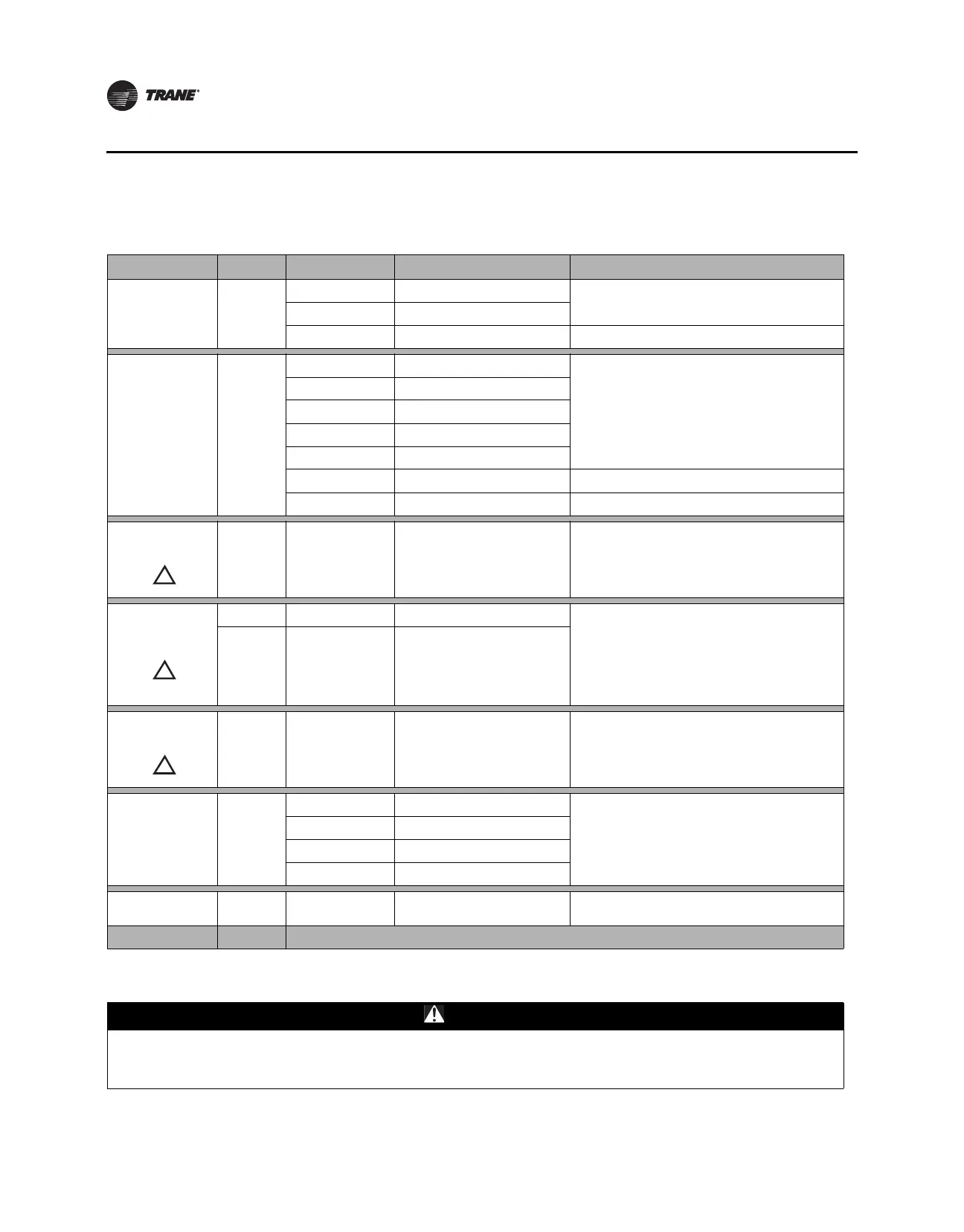
The following table provides information about the types of device connections.
Connection Quantity Types Range Notes
Analog input
(AI1 to AI5)
5
Temperature 10 kthermistor
AI1 to AI4 can be configured for timed override
capability.
Setpoint 189 to 889
Resistive 100 to 100 k Typically used for fan speed switch.
Universal input
(UI1 and UI2)
2
Linear 0–20 mA
These inputs may be configured to be thermistor or
resistive inputs, 0–10 Vdc inputs, or 0–20 mA inputs.
Linear 0–10 Vdc
Temperature 10 kthermistor
Setpoint 189 to 889
Resistive 100 to 100 k
Binary Open collector/dry contact Low impedance relay contacts recommended.
Pulse Solid state open collector Minimum dwell time is 25 ms On and 25 ms Off.
Binary input (BI1 to
BI3) See CAUTION
below.
3 24 Vac detect
The UC400 controller provides the 24 Vac that is
required to drive the binary inputs when using the
recommended connections.
Binary output (BO1
to BO3) See
CAUTION below.
3 Relay 2.88 A @24 Vac pilot duty
Power needs to be wired to the binary output. All
outputs are isolated from each other and from ground
or power. Ranges given are per contact.
Other
Ranges
• General purpose
(resistive)
• Motor duty
(inductive)
• 10 A max up to 277 Vac
• 10 A max up to 30 Vdc
• 1/3 hp @125 Vac (7.5 A max)
• 1/2 hp @277 Vac (7.5 A max)
Binary output (BO4
to BO9) See
CAUTION below.
6TRIAC
0.5 A max @24-277 Vac, resistive
and pilot duty
Use for modulating TRIAC. User determines whether
closing high side (providing voltage to the grounded
load) or low side (providing ground to the power load).
Ranges given are per contact and power comes from
TRIAC SUPPLY circuit.
Analog output/
binary input
(AO1/BI4 and
AO2/BI5)
2
Linear output 0–20 mA
Each termination must be configured as either an
analog output or binary input.
Linear output 0–10 Vdc
Binary input Dry contact
PWM output 80 Hz signal @ 15 Vdc
Pressure inputs
(PI1 and PI2)
2 3-wire 0–5 in H
2
O
Pressure inputs supplied with 5 volts of power.
Designed for Kavlico™ pressure transducers.
Overall Point Total 23
CAUTION
Electrical Hazard!
Do Not mix Class 1 and Class 2 voltage wiring in an enclosure or on a controller without an approved barrier
between the wiring.
!
!
!