VAV-SVX07B-EN 55
Calibration, Operation Modes, and Control
• When the supply airflow is greater than the active minimum flow setpoint, plus 5% of the
configured nominal airflow.
In pressure dependent mode, the air valve position is substituted for the supply airflow.
Parallel Fan Operation During Calibration
During calibration, the parallel fan is in the same state (ON or OFF) prior to the start of calibration.
It remains in that state until one minute after calibration ends. One minute after calibration ends,
normal control of the parallel fan resumes. The one-minute period is ignored if reheat is active or
if the parallel fan is overridden.
Fan OFF Delay
There is a 15-second fan OFF delay. When reheat is turned OFF, the controller turns the fan OFF 15
seconds later.
Ventilation Flow Control (VFC)
Ventilation flow control is applied to a VAV terminal and used to temper cold outdoor air (OA) that
is brought into a building for ventilation purposes. The tempered air is intended to supply an air
handler unit (AHU), which provides comfort control to the zones it serves. The VAV terminal
supplies the correct amount of ventilation air and, when possible, tempers the ventilation air to
reduce the load on the air handler. Refer to the following table for ventilation flow control outputs.
The ventilation flow control process is a constant volume, variable temperature process. Single
duct VAV units with either electric or hot water reheat are used. Fan-powered units are not used
for ventilation flow control. Ventilation flow control must have a temperature sensor that is located
and setup as a discharge air temperature sensor. The required range of discharge air temperature
setpoints is from 19°F to 70°F (-7.22°C to 21.11°C).
Ventilation flow control staged reheat control (electric or hot water) achieves a 30-minute average
discharge air temperature to within ±5°F (±2.78°C) of the discharge air temperature setpoint when
the inlet temperature is within the control range. Ventilation flow control modulating reheat control
(hot water only) achieves a discharge air temperature to within ±5°F (±2.78°C) of the discharge air
temperature setpoint when the inlet temperature is within the control range.
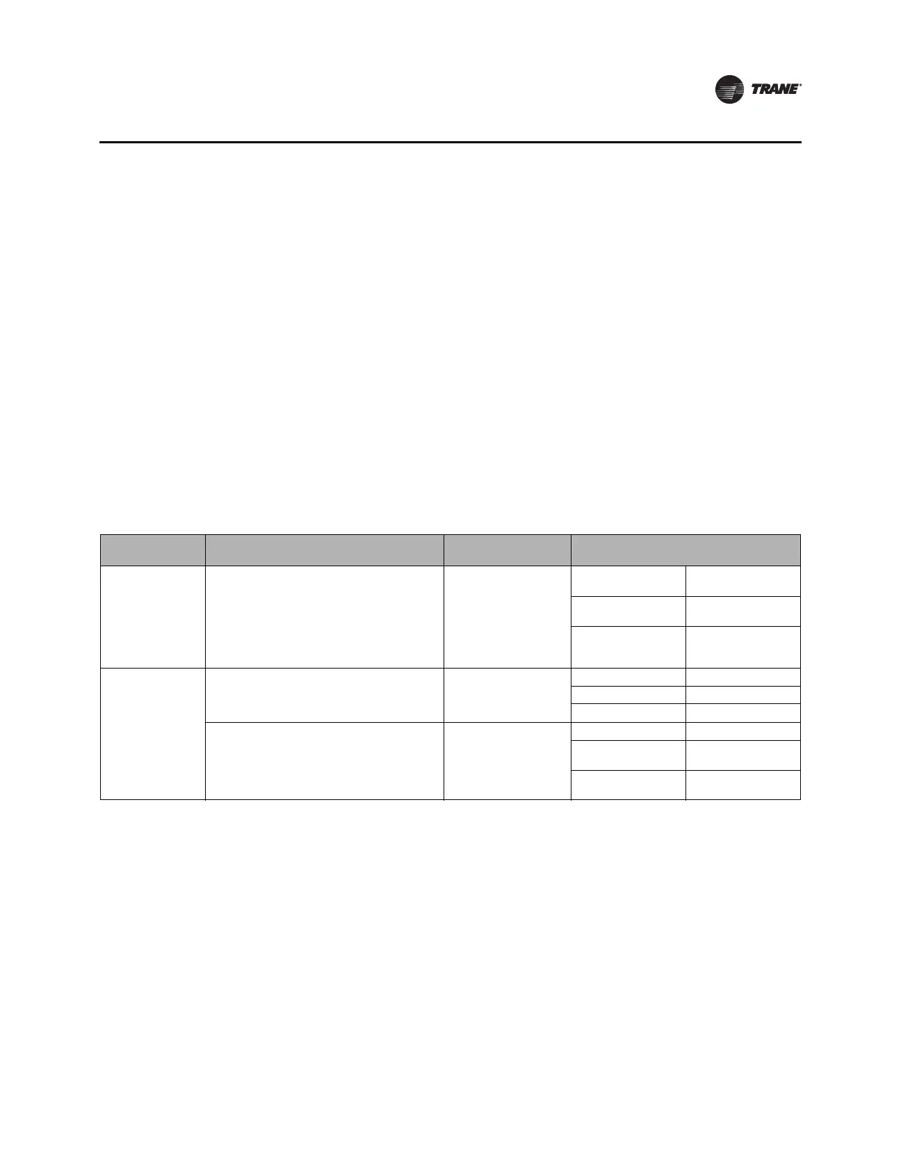
Table 8. Ventilation Flow Control Outputs
Occupancy
Mode Source Temperature Air Valve Control Reheat Control
Occupied, Occupied
Standby, or Occupied
Bypass
Any
Constant volume (if valid,
communicated
ventilation setpoint; if not
valid, configured
ventilation setpoint)
Electric
VFC staged reheat
control
Staged hot water
VFC staged reheat
control
Modulating hot water
VFC modulating reheat
control (same as STC
capacity control)
Unoccupied
Communicated source temperature (if valid; if
not valid, discharge air temperature) greater
than configured OA low limit.
Closed, 0%
Electric Off
Staged hot water Off
Modulating hot water Off
Communicated source temperature (if valid; if
not valid, discharge air temperature) less than
configured OA low limit.
Closed, 0%
Electric Off
Staged hot water
On, 100% freeze
protection
Modulating hot water
On, 100% freeze
protection