68 VAV-SVX07B-EN
Troubleshooting
CO
2
Sensor Failure
In the event that the UC400 controller reports an incorrect or failed CO
2
sensor input temperature,
check the following:
• Check that the CO
2
point is not out of
service.
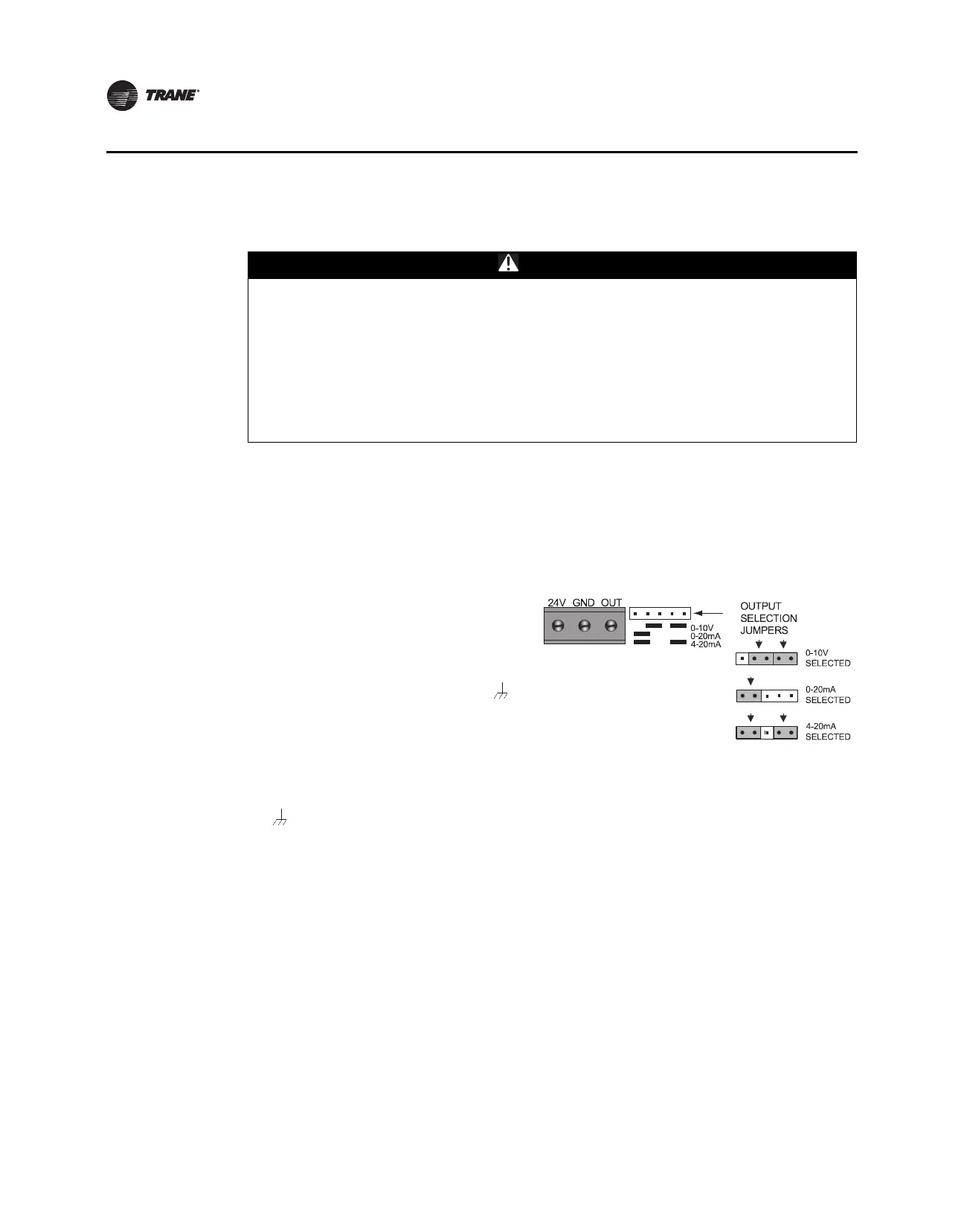
• Check jumper position on CO
2
sensor.
– UC400 default is 4–20 mA.
Note: If the CO
2
sensor is not set up for
4 –20 mA, the CO
2
input can be put
out of service with Tracer TU,
changed to the 0–20 mA or 0–10
Vdc in the configuration screen,
and then put back in service.
– Check voltage between UI2 and
with the sensor connected. It should
be between 1-10V DC. If it is not, check
incoming power.
– Check voltage input to CO
2
sensor
with voltmeter. It should be between 20.4 to 27.6 Vac; nominal is 24 Vac.
• After measuring the proper voltage at incoming power, and there is no VDC output at UI2 and
, replace sensor. If there is no voltage, check up stream of controller to see were voltage has
been interrupted. Refer to the section, “Appendix: Typical Trane Factory Wiring Diagrams,”
p. 77.
WARNING
Hazardous Service Procedures!
The maintenance and troubleshooting procedures recommended in this section of the manual
could result in exposure to electrical, mechanical or other potential safety hazards. Always
refer to the safety warnings provided throughout this manual concerning these procedures.
When possible, disconnect all electrical power including remote disconnect and discharge all
energy storing devices such as capacitors before servicing. Follow proper lockout/tagout
procedures to ensure the power can not be inadvertently energized. When necessary to work
with live electrical components, have a qualified licensed electrician or other individual who
has been trained in handling live electrical components perform these tasks. Failure to follow
all of the recommended safety warnings provided, could result in death or serious injury.