VAV-SVX07B-EN 17
Wiring Installation
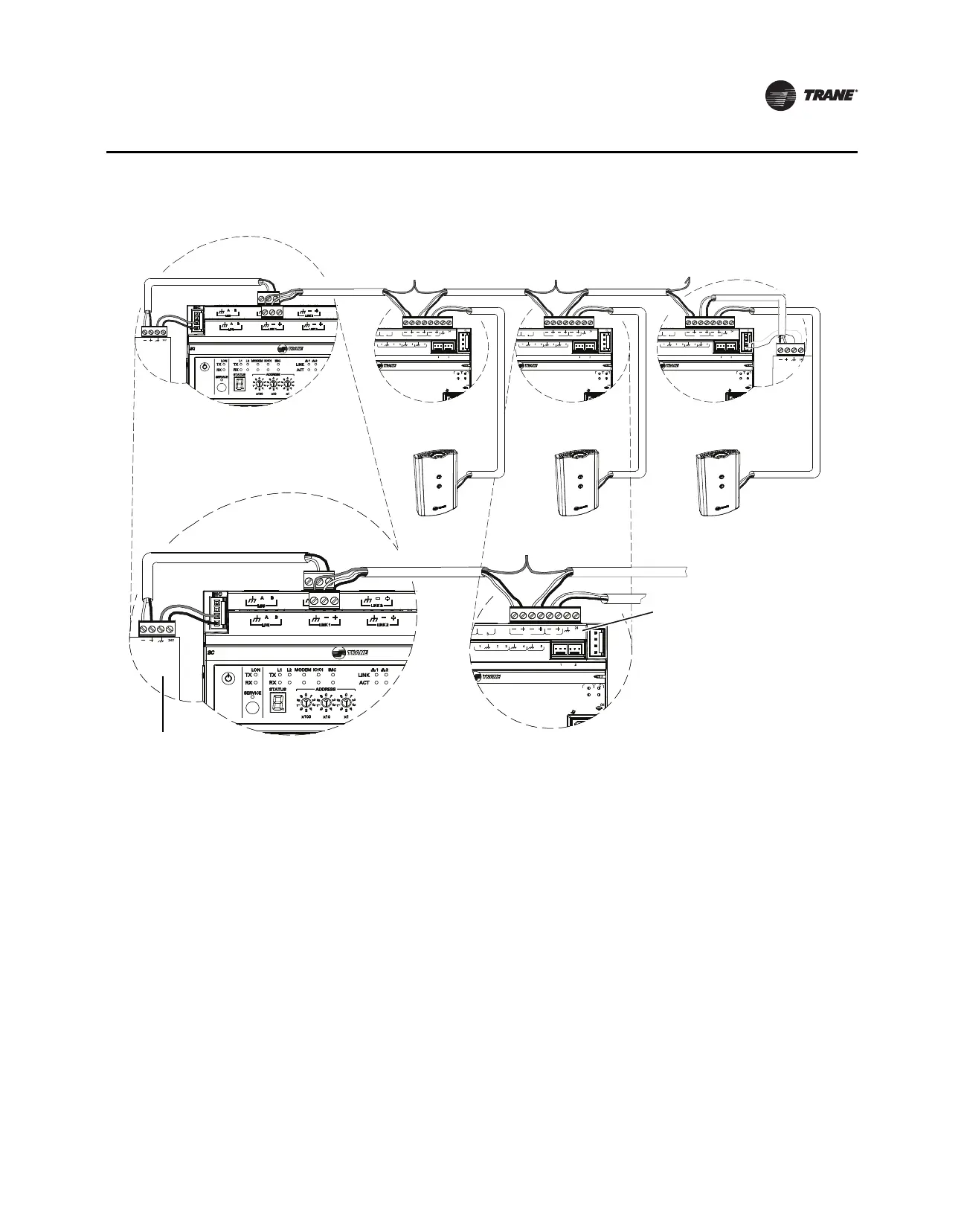
Figure 1. BACnet MS/TP Link Wiring
Wiring Best Practices
To ensure proper network communication, follow the recommended wiring and best practices
below when installing communication wire:
• All wiring must comply with the National Electrical Code™ (NEC) and local codes.
• Ensure that 24 Vac power supplies are consistent in regards to grounding. Avoid sharing 24 Vac
between controllers.
• Avoid over tightening cable ties and other forms of cable wraps. This can damage the wires
inside the cable.
• Do not run communication cable alongside or in the same conduit as 24 Vac power. This
includes the conductors running from TRIAC-type inputs.
• In open plenums, avoid running wire near lighting ballasts, especially those using 277 Vac.
• Use same communication wire type, without terminators, for the zone sensor communication
stubs from the UC400 controller IMC terminals to the zone sensor communication module.
• Zone Sensor communication wiring length limits of 300 ft. (100 m).
Note: For more details, refer to the Unit Controller Wiring for the Tracer SC™ System Controller
Wiring Guide (BAS-SVN03).
BI LINK IMC
+
VDC
AIAIAI AI AI
PP
TX
RX
LINK IM
SERVI
SERVICE TOOL
IM
BI LINK IMC
+
VDC
AIAIAI AI AI
PP
TX
RX
LINK IM
SERVI
SERVICE TOOL
IM
BI LINK IMC
+
VDC
AIAIAI AI AI
PP
TX
RX
LINK IM
SERVI
SERVICE TOOL
IM
+
+
BI LINK IMC
+
VDC
AIAIAI AI AI
PP
TX
RX
LINK IM
SERVI
SERVICE TOOL
IM
+
BI LINK IMC
+
VDC
AIAIAI AI AI
PP
TX
RX
LINK IM
SERVI
SERVICE TOOL
IM
+
Tracer SC UC400 UC400 UC400
Zone
Sensor
Zone
Sensor
Zone
Sensor
Trane BACnet terminator
Zone sensor
communications
jack wiring