FMS-2000M
LIT-12013580
25
1. Shut down the FMS-1655M unit and remove the monitor from the wall.
2. Remove the back cover from the display enclosure.
3. Unplug the 4-position terminal block from the display circuit board, with the wires from the interface cable still connected. If you use
a BACnet network, unplug the 3-position terminal block.
4. Prepare the opening in the wall for the mounting display unit. For instructions, refer to the FMS-2000M Critical Environment Monitor
Installation Guide (LIT-12013555).
5. Pull the existing FMS-1655M monitor cables through the opening in the wall.
6. At the back of the FMS-2000M monitor, remove the 4-position terminal block plug from the pin header. If you use a BACnet
network, then remove the 3-position terminal block as well.
7. Connect the 4-position terminal block at the end of the interface cable to the 4-pin header at the back of the FMS-2000M display. If
you use a BACnet network, connect the networking cable to the 3-pin header. See Figure 11.
8. To complete the installation, refer to the FMS-2000M Critical Environment Monitor Installation Guide (LIT-12013555).
Upgrading an FMS-1655M monitor to an FMS-2000M monitor
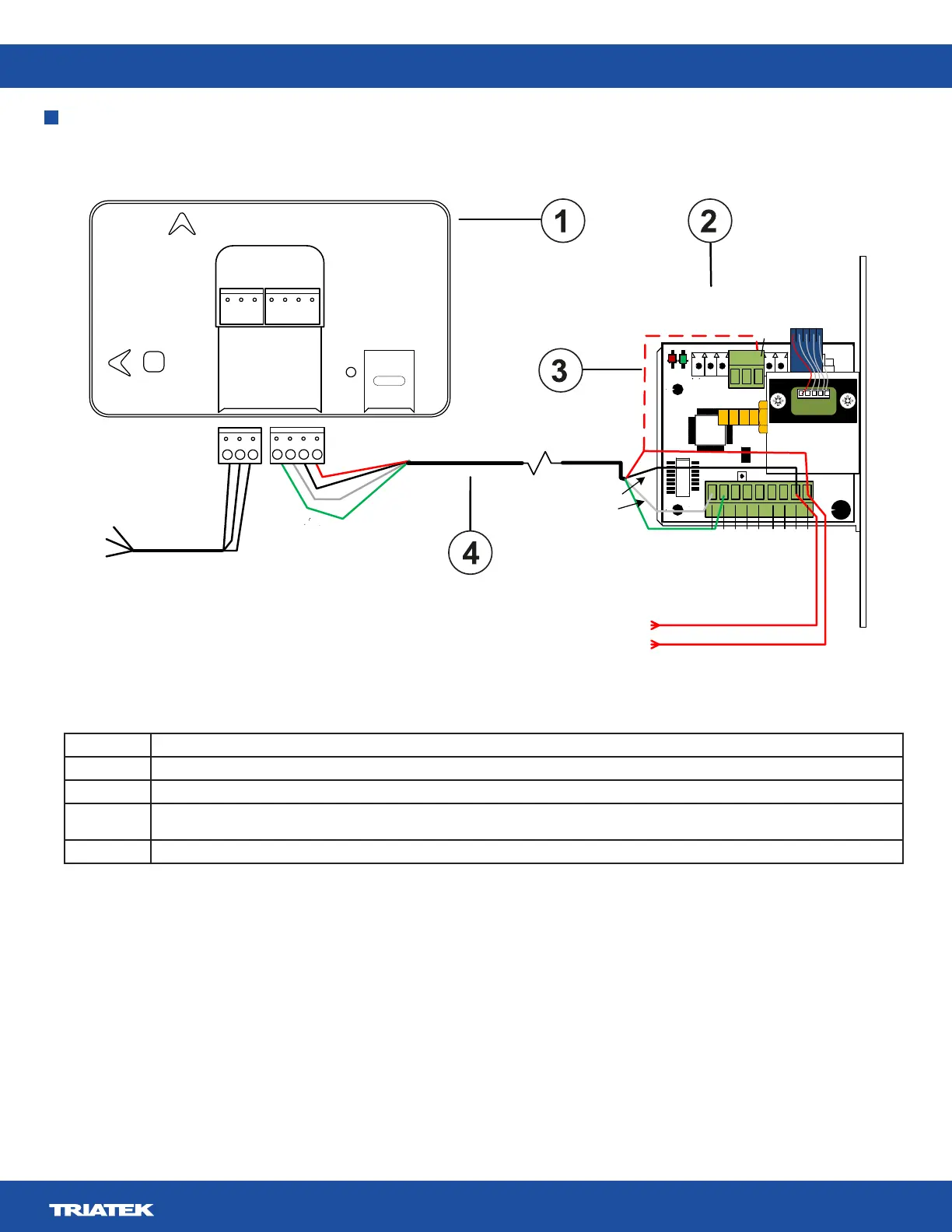
Callout Description
1 FMS-2000M monitor
2 FMS-1655M remote sensor
3 Red display power wire. If the sensor includes a 3 position terminal block with display power installed, remove the wire and connect it
at the +Vin terminal of the 9 position terminal block as shown.
4 Display-to-sensor interface cable. Supplied cable: 10 ft
17
1
U2
33
49
7
5
1
CN1
S2
SW1
+Vin
-Vin
Vo
Io
+Vs
IN
GND
-
+
RS485
2
1
4
3
ADDR
6
JP4
LED1
LED2
RUN
PWR
JP5
CN3
5
JP2
24 VAC input
from power source
To BAS
Network
-
+
22 AWG stranded 3-wire
twisted pair, shielded
Green
White
Black
Red
Green
White
Black
Red
}
Power input
P1
P2
BACnet MS/TP
Display_PWR
NC = No Connection
NC
NC
+
-
+
-
+
-
REF
24V_IN
DSPLY
RS485
BACnet
MS/TP
Landscape
Portrait
Ref.
Table 10: Ugrade wiring diagram callouts
Figure 11: Wiring the FMS-2000M to an FMS-1655M remote sensor