CONTROLS AND INDICATORS
(40)TRIG'D
This green LED lights when the B trigger source signal
cau-
ses the B triggered sweep to be initiated.
(41 )CH4 or 8 EXT TRIG
Input connector for the CH4 signal; serves also as the B
TRIG external input connector. CH4 signal may be obser-
ved simultaneously with CH1, 2 and 3 signals when the
QUAD mode is selected. When the SOURCE select
con-
trol is set to either EXT (CH4) 1/1. or 1/10, the trigger
source is this input signal.
(42)TRIG MODE
This control selects the Trigger Mode. A corresponding
LED lights to indicate which mode has been selected.
AUTO Sweep is initiated in triggered operation but
the trace is sweept even in the absence of a
trigger signal. When the HORIZONTAL
DISPLAY is set to DUAL, the B sweep is set to
AUTO.
NORM Triggered operation but no trace is presented
when a proper trigger signal is not applied.
SINGLE Single sweep operation. Note that in this mo-
de,
simultaneous observation of both the A
and B Sweeps is not possible.
rCAUTION: ,
For dual or quad trace, single sweep operation
MODE must not be set to ALT. Use the CHOP
mode instead.
RESET This is the reset button for single sweep opera-
tion.
Its LED remains lighted until the main A
Sweep ends.
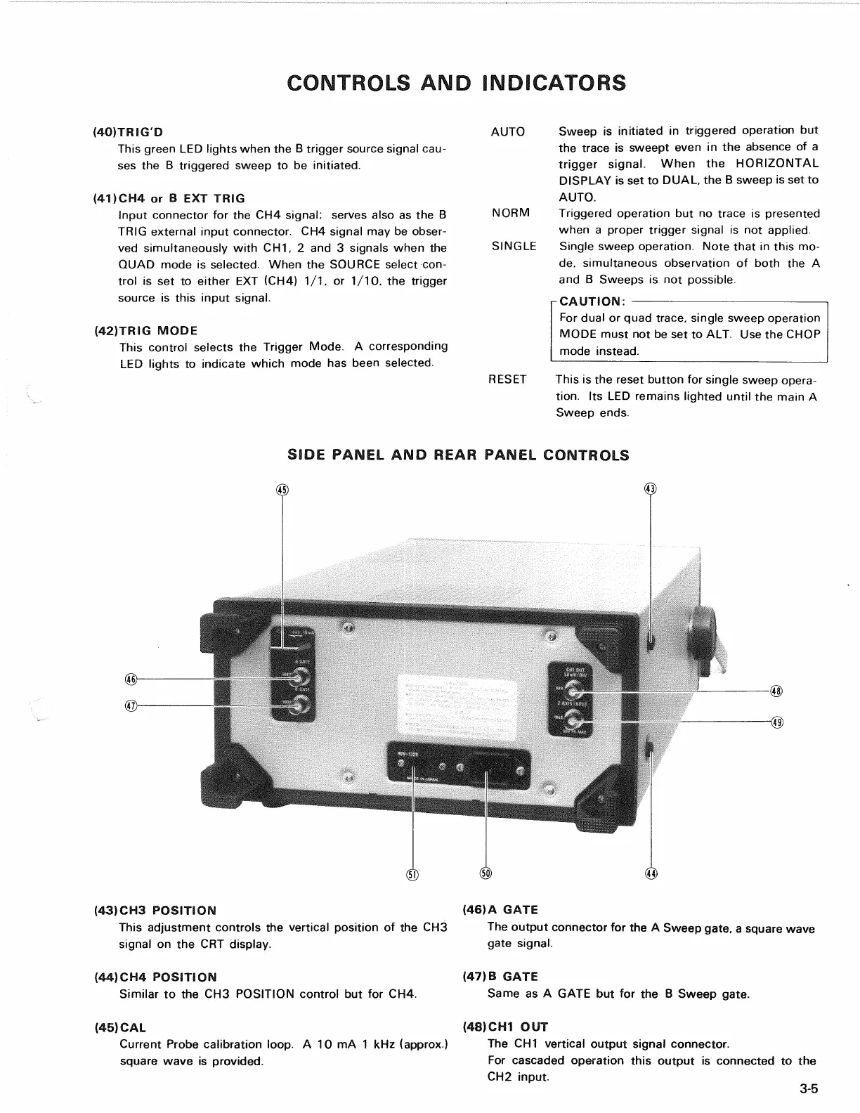
SIDE PANEL AND REAR PANEL CONTROLS
(43) CH3 POSITION
This adjustment controls the vertical position of the CH3
signal on the CRT display.
(44) CH4 POSITION
Similar to the CH3 POSITION control but for CH4.
(45) CAL
Current Probe calibration loop. A 10 mA 1 kHz (approx.)
square wave is provided.
(46) A GATE
The output connector for the A Sweep gate, a square wave
gate signal.
(47) B GATE
Same as A GATE but for the B Sweep gate.
(48) CH1 OUT
The CH1 vertical output signal connector.
For cascaded operation this output is connected to the
CH2 input.
3-5