OPERATION
Note that for this type of operation both the DELAY TIME
MULTIPLIER and TRIG LEVEL affect the start of the sweep
so that the delay time is used as a reference point.
14] ALTERNATING SWEEP OPERATION
A Sweep and B Sweep are usable in an alternating fashion ma-
king it possible to observe both the normal and magnified wa-
veform simultaneously.
Procedure:
1.
Set the HORIZONTAL DISPLAY to A and adjust the CS-
2100A for a normal waveform display.
2.
Pull out the SLOPE PULL STARTS AFTER DELAY control
and set the HORIZONTAL DISPLAY to ALT. Adjust
TRACE SEP (30) for easy observation of both the A and B
traces.
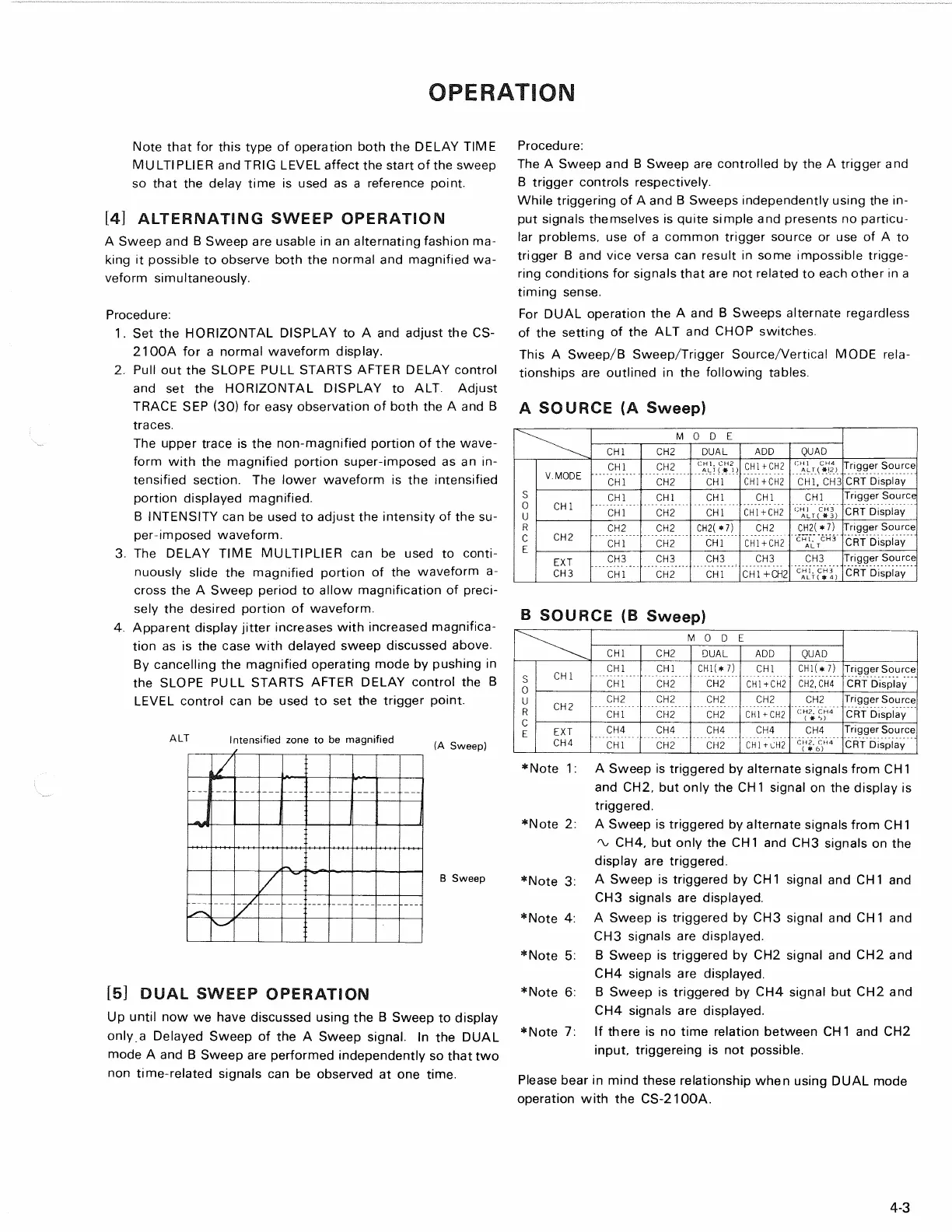
The upper trace is the non-magnified portion of the wave-
form with the magnified portion super-imposed as an in-
tensified section. The lower waveform is the intensified
portion displayed magnified.
B INTENSITY can be used to adjust the intensity of the su-
per-imposed waveform.
3. The DELAY TIME MULTIPLIER can be used to conti-
nuously slide the magnified portion of the waveform a-
cross the A Sweep period to allow magnification of preci-
sely the desired portion of waveform.
4.
Apparent display jitter increases with increased magnifica-
tion as is the case with delayed sweep discussed above.
By cancelling the magnified operating mode by pushing in
the SLOPE PULL STARTS AFTER DELAY control the B
LEVEL control can be used to set the trigger point.
B Sweep
15]
DUAL SWEEP OPERATION
Up until now we have discussed using the B Sweep to display
only a Delayed Sweep of the A Sweep signal. In the DUAL
mode A and B Sweep are performed independently so that two
non time-related signals can be observed at one time.
Procedure:
The A Sweep and B Sweep are controlled by the A trigger and
B trigger controls respectively.
While triggering of A and B Sweeps independently using the in-
put signals themselves is quite simple and presents no particu-
lar problems, use of a common trigger source or use of A to
trigger B and vice versa can result in some impossible trigge-
ring conditions for signals that are not related to each other in a
timing sense.
For DUAL operation the A and B Sweeps alternate regardless
of the setting of the ALT and CHOP switches.
This A Sweep/B Sweep/Trigger Source/Vertical MODE rela-
tionships are outlined in the following tables.
A SOURCE (A Sweep)
•Note 1: A Sweep is triggered by alternate signals from CH 1
and CH2, but only the CH1 signal on the display is
triggered.
*Note 2: A Sweep is triggered by alternate signals from CH 1
CH4,
but only the CH
1
and CH3 signals on the
display are triggered.
*Note 3: A Sweep is triggered by CH1 signal and CH1 and
CH3 signals are displayed.
*Note 4: A Sweep is triggered by CH3 signal and CH1 and
CH3 signals are displayed.
•Note 5: B Sweep is triggered by CH2 signal and CH2 and
CH4 signals are displayed.
•Note 6: B Sweep is triggered by CH4 signal but CH2 and
CH4 signals are displayed.
•Note 7: If there is no time relation between CH1 and CH2
input, triggereing is not possible.
Please bear in mind these relationship when using DUAL mode
operation with the CS-2100A.
4-3
B SOURCE (B Sweep)
M ODE
CHI CH2 DUAL
ADD QUAD
V.MODE
CHI
CH2
CH1.
CH2
ALT { * 1 )
CH1+CH2
CHI CH4
ALT(*(2)
Trigger Source
V.MODE
CHI CH2
CHI CH1+CH2
CHI,
CH3
CRT Display
s
0
u
CHI
CHI
CHI CHI
CHI CHI
Trigger Source
s
0
u
CHI
CHI
CH2
CHI
CH1+CH2
CHI C H 3
ALT ( * 3)
CRT Display
R
CH2
CH2 CH2
CH2(*7) CH2
CH2(*7) Trigger Source
C
E
CH2
CHI CH2
CHI
CH1+CH2
CHI.
CH 3
ALT
CRT Display
EXT
CH3 CH3 CH3 CH3
CH3
Trigger Source
CH3
CHI CH2
CHI
CH1+CH2
CHI,
CH 3
ALT
(
* 4)
CRT Display
MODE
CHI
CH2
DUAL ADD
QUAD
CHI
CHI CHI
CH1(*
7) CHI
CH1(*7)
Trigger Source
S
0
u
CHI
CHI
CH2
CH2 CH1+CH2
CH2.CH4
CRT Display
S
0
u
CH2
CH2
CH2 CH2 CH2
CH2
Trigger Source
R
C
E
CH2
CHI
CH2 CH2 CH1+CH2
CH2.
CH4
(
* ">)
CRT Display
R
C
E
EXT
CH4
CH4 CH4 CH4 CH4
Trigger Source
CH4
CHI
CH2
CH2
CH1+CH2
CH2.
CH4
( # 6)
CRT Display
Intensified zone to be magnified
(A Sweep)
ALT