OPERATION
A Trigger
1) The SOURCE control selects the signal to be used.
With the V. MODE the source is determined by the
setting of the Vertical MODE.
As mentionned above, if CHOP has been selected,
the trigger source is the chopping signal itself, mak-
ing waveform observation impossible. Use ALT
instead in this case. If SOURCE is set to CH1 or
CH2,
regardless of the setting of MODE, CH
1
or
CH2 signal provides the trigger source.
If SOURCE is set to EXT (CH3) 1/1. or 1/10, ex-
cept for QUAD operation, the signal applied to the
CH3 or A EXT TRIG input (36) is the trigger
source. For QUAD operation this input is taken as
the CH3 signal and can be observed as the trigger
waveform.
2) After setting SOURCE, adjust the LEVEL/SLOPE
(34) control to set the trigger point. Sync is indica-
ted by the green LED lighting.
As necessary to obtain a stable synchronized signal
display, adjust HOLDOFF (30) and COUPLING
(33).
If the SLOPE control is pulled out, the trigger level
is put into the FIX mode with the trigger point at
the center of the waveform.
5. Adjust the A SWEEP TIME/DIV (26) control for an appro-
priate display of the signal input. If required, use the A
VAR (27) control as
well.
This completes the adjustment procedure for normal A
Sweep display operation.
[2] MAGNIFIED SWEEP OPERATION
Since merely shortening the sweep time to magnify a portion of
an observed waveform can result in the desired portion disap-
pearing off the screen, such magnified display should be perfor-
med using the MAGNIFIED SWEEP.
Procedure:
Using the POSITION control, adjust the desired portion of
waveform to the center of the CRT. Pull out the FINE PULL
X10 MAG (31) control to magnify the display 10 times. For
this type of display the sweep time is the SWEEP TIME/DIV
setting divided by 10.
[3] DELAYED SWEEP OPERATION
Delayed sweep operation is achieved by use of both the A
Sweep and the B Sweep.
Procedure:
1.
First set the HORIZONTAL DISPLAY to A and adjust the
CS-2100A for a normal waveform display.
2.
Pull out the SLOPE PULL STARTS AFTER DELAY (39)
control to set the sweep in the STARTS AFTER DELAY
mode.
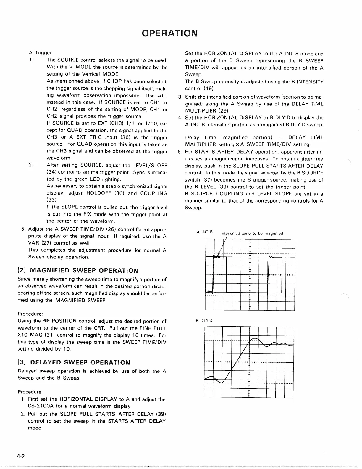
Set the HORIZONTAL DISPLAY to the A-INT-B mode and
a portion of the B Sweep representing the B SWEEP
TIME/DIV will appear as an intensified portion of the A
Sweep.
The B Sweep intensity is adjusted using the B INTENSITY
control (19).
3. Shift the intensified portion of waveform (section to be ma-
gnified) along the A Sweep by use of the DELAY TIME
MULTIPLIER (29).
4.
Set the HORIZONTAL DISPLAY to B DLY'D to display the
A-INT-B intensified portion as a magnified B DLY'D sweep.
Delay Time (magnified portion) = DELAY TIME
MALTIPLIER setting x A SWEEP TIME/DIV setting.
5. For STARTS AFTER DELAY operation, apparent jitter in-
creases as magnification increases. To obtain a jitter free
display, push in the SLOPE PULL STARTS AFTER DELAY
control.
In this mode the signal selected by the B SOURCE
switch (37) becomes the B trigger source, making use of
the B LEVEL (39) control to set the trigger point.
B SOURCE. COUPLING and LEVEL SLOPE are set in a
manner similar to that of the corresponding controls for A
Sweep.
Intensified zone to be magnified
B DLY'D
4-2
A-INT-B