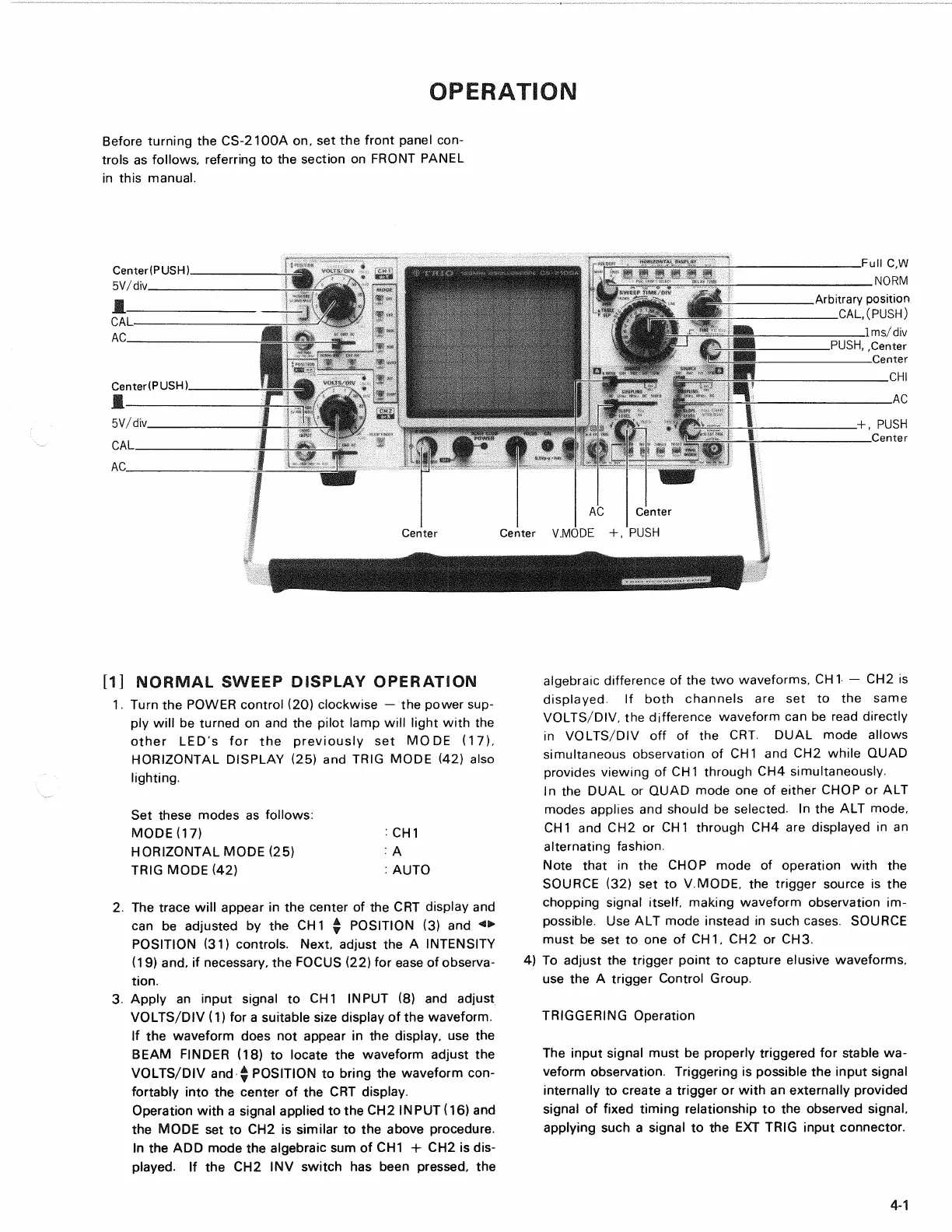
OPERATION
Before turning the CS-2100A on, set the front panel
con-
trols as follows, referring to the section on FRONT PANEL
in this manual.
[1] NORMAL SWEEP DISPLAY OPERATION
1.
Turn the POWER control (20) clockwise — the power sup-
ply will be turned on and the pilot lamp will light with the
other LED's for the previously set MODE (17),
HORIZONTAL DISPLAY (25) and TRIG MODE (42) also
lighting.
Set these modes as follows:
MODE07) : CH 1
HORIZONTAL MODE (25) : A
TRIG MODE (42) : AUTO
2.
The trace will appear in the center of the CRT display and
can be adjusted by the CH
1
^ POSITION (3) and <>
POSITION (31) controls. Next, adjust the A INTENSITY
(19) and, if necessary, the FOCUS (22) for ease of observa-
tion.
3. Apply an input signal to CH1 INPUT (8) and adjust
VOLTS/DIV (1) for a suitable size display of the waveform.
If the waveform does not appear in the display, use the
BEAM FINDER (18) to locate the waveform adjust the
VOLTS/DIV and $ POSITION to bring the waveform con-
fortably into the center of the CRT display.
Operation with a signal applied to the CH2 INPUT (16) and
the MODE set to CH2 is similar to the above procedure.
In the ADD mode the algebraic sum of CH1 + CH2 is dis-
played.
If the CH2 INV switch has been pressed, the
algebraic difference of the two waveforms, CH1 — CH2 is
displayed.
If both channels are set to the same
VOLTS/DIV, the difference waveform can be read directly
in VOLTS/DIV off of the CRT. DUAL mode allows
simultaneous observation of CH1 and CH2 while QUAD
provides viewing of CH1 through CH4 simultaneously.
In the DUAL or QUAD mode one of either CHOP or ALT
modes applies and should be selected. In the ALT mode,
CH1 and CH2 or CH1 through CH4 are displayed in an
alternating fashion.
Note that in the CHOP mode of operation with the
SOURCE (32) set to V.MODE, the trigger source is the
chopping signal itself, making waveform observation im-
possible. Use ALT mode instead in such cases. SOURCE
must be set to one of CH 1, CH2 or CH3.
4) To adjust the trigger point to capture elusive waveforms,
use the A trigger Control Group.
TRIGGERING Operation
The input signal must be properly triggered for stable wa-
veform observation. Triggering is possible the input signal
internally to create a trigger or with an externally provided
signal of fixed timing relationship to the observed signal,
applying such a signal to the EXT TRIG input connector.
4-1