CLASS B
+
& C MOTORHOME
68
10.6 FUSE PANELS
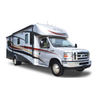
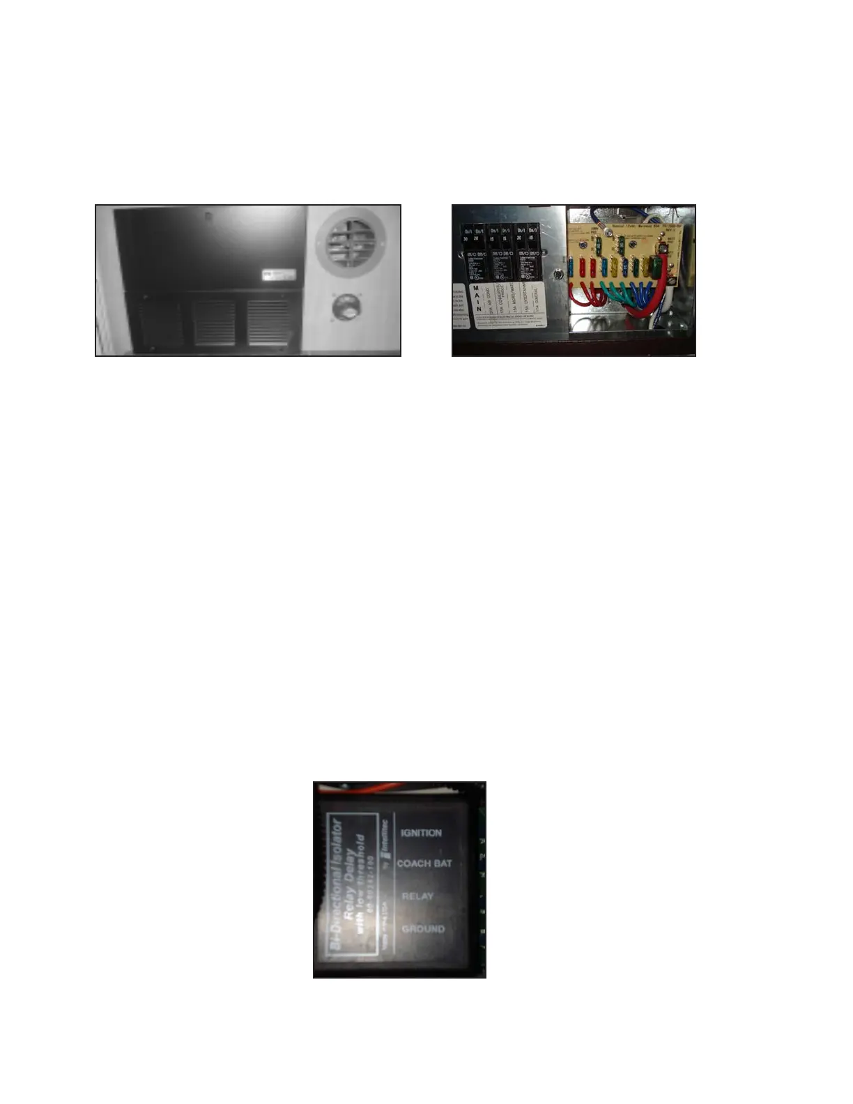
10.6.1 COACH FUSE PANEL
The coach fuse panel is located in the distribution panel on the end of the Galley cabinet. See the label on the face of the
fuse panel for fuse size and function identication.
10.6.2 CHASSIS FUSE PANEL
See the Chassis Manufacturer's Owner's Manual in the Owner Information Package to identify the fuse or circuit breaker
location, size and function.
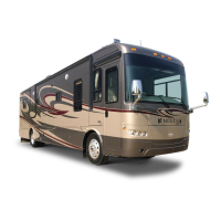
10.6.3 B.I.R.D. (BI-DIRECTIONAL ISOLATOR RELAY DELAY)
The Bi-Directional Isolator Relay Delay constantly senses the voltage on the coach and chassis batteries. If either voltage
is above 13.3 volts, which indicates the batteries are being charged, the control closes the isolator relay. This parallels the
batteries, charging them both. If the ignition is OFF and the voltage falls below 12.8 volts for approximately ve seconds,
the relay will open to prevent the coach loads from discharging the chassis battery. When the voltage goes back above 13.3
volts, the relay will close again.
If the ignition is ON and the voltage falls below 12.0 volts for approximately ve seconds, the relay will open to prevent the
coach loads from overloading the alternator and discharging the chassis battery. When the voltage on the chassis goes
back above 13.3 volts, the relay will close again. Allowing the batteries to stay connected together to a lower voltage helps
charge a heavily discharged coach more quickly with the varying output of the alternator.
A lockout lead is provided to prevent conicts if both the converter/genset and the alternator are trying to charge the bat-
teries at the same time.
DISTRIBUTION PANEL
120V CIRCUIT BREAKERS AND 12V
COACH FUSES