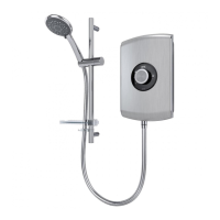
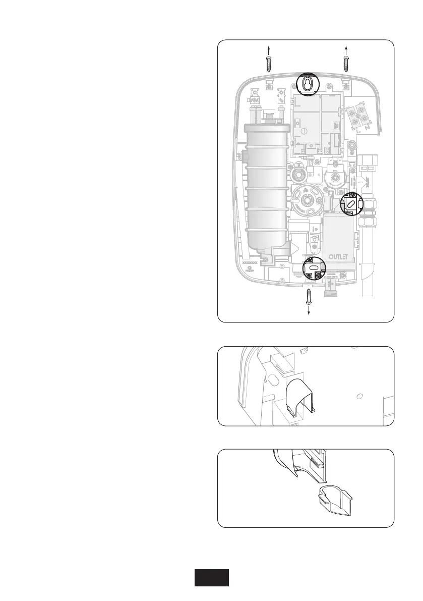
Fig.7
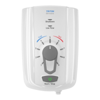
Fig.8
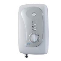
Fig.9
Note: The control knobs are an integral part of
the cover – DO NOT attempt to remove them.
Unscrew the two top and one bottom retaining
screws (fig.7) and lift the cover from the
backplate.
Entry positions for the mains water and electric
cable are from the top, bottom, or from the
back.
Note: Deviations from the designated entry
points will invalidate product approvals.
If bottom entry has been chosen, fit the
appropriate cut-out in the top of the backplate
(fig.8).
If top entry has been chosen, fit the appropriate
cut-out in the bottom of the cover (fig.9).
After choosing the site for the shower, use the
Installation Template supplied to mark the three
fixing holes, the position of which are shown in
(fig.7).
Drill and plug to suit the fixing screws supplied.
(The wall plugs provided are suitable for most
brick walls — use an appropriate masonry drill,
but if the wall is plasterboard or a soft building
block, you must use suitable wall plugs and an
appropriate drill bit).
Screw the top fixing screw into position leaving
the base of the screw head protruding 6 mm out
from the wall.
Hook the backplate over the top screw and fit the
other fixing screw into position.
DO NOT fully tighten the screws at this stage,
as the fixing holes are elongated to allow for
out of square adjustment after the plumbing
connections have been completed.
Fitting the Shower to the Wall
 Loading...