Home
Triton
Bathroom Fixtures
Safeguard
Triton Safeguard User Manual
5
of 1
of 1 rating
40 pages
Give review
Manual
Specs
To Next Page
To Next Page
To Previous Page
To Previous Page
Loading...
4
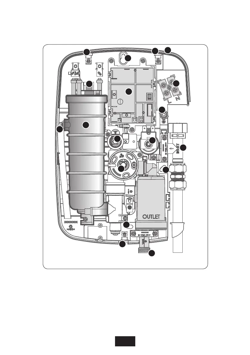
Note:
Wires have not been shown for reasons of clarity
.
1
2
2
2
3
3
3
4
5
6
12
9
14
10
7
8
11
13
Inside the unit
(fig.1)
1.
T
op cable/pipe entry
2.
W
all screw fixings
3.
Cover screw fixings
4.
Thermal safety cut-out
5.
P
ow
er
p
r
i
n
t
e
d
c
i
r
cu
it
b
o
a
r
d
6.
C
a
n
a
n
d
e
l
e
m
e
n
t
a
s
s
e
m
b
l
y
7.
Flow switch assembly
8.
T
emperature Control
9.
T
erminal block
10.
Earth connection
11.
Solenoid valve
12.
Water inlet
13.
Press
ure
reli
ef d
evic
e
(PR
D)
14.
Shower outlet
Main Components
Inside the unit
(fig.1)
5
7
Table of Contents
Table of Contents
2
Important Safety Information
3
Introduction
5
Specifications
5
Advice to Users
5
Main Components
6
Electrical Requirements
8
How to Operate the Shower
10
Water Requirements
14
Siting of the Shower
15
Fitting the Shower to the Wall
16
Plumbing Connections
17
Electrical Connections
19
Whale Pump (Not Supplied)
20
Commissioning
21
PCB Dip Switch Settings
23
Replacing the Cover
24
Operating Functions
25
Instructions for Installers and Service Engineers Only
26
Spare Parts
27
Fault Finding
29
In-Service Testing (Safeguard T100 Care Only)
31
Service Policy
39
5
Based on 1 rating
Ask a question
Give review
Questions and Answers:
Need help?
Do you have a question about the Triton Safeguard and is the answer not in the manual?
Ask a question
Triton Safeguard Specifications
General
Type
Electric Shower
Material
Plastic
Color
White
Installation
Wall Mounted
Cable Entry Points
Bottom
Dimensions
200 x 200 x 90 mm
Related product manuals
Triton Safeguard+
2 pages
Triton ENVI
20 pages
Triton Opal
33 pages
Triton Kaho
16 pages
Triton ELINA
28 pages
Triton T90SR
32 pages
Triton AMORE
28 pages
Triton Omnicare
40 pages
Triton Martinique
28 pages
Triton LocBoard LB2
3 pages
Triton LocBoard LB2-B
2 pages
Triton T80ZFF FAST-FIT
28 pages
 Loading...