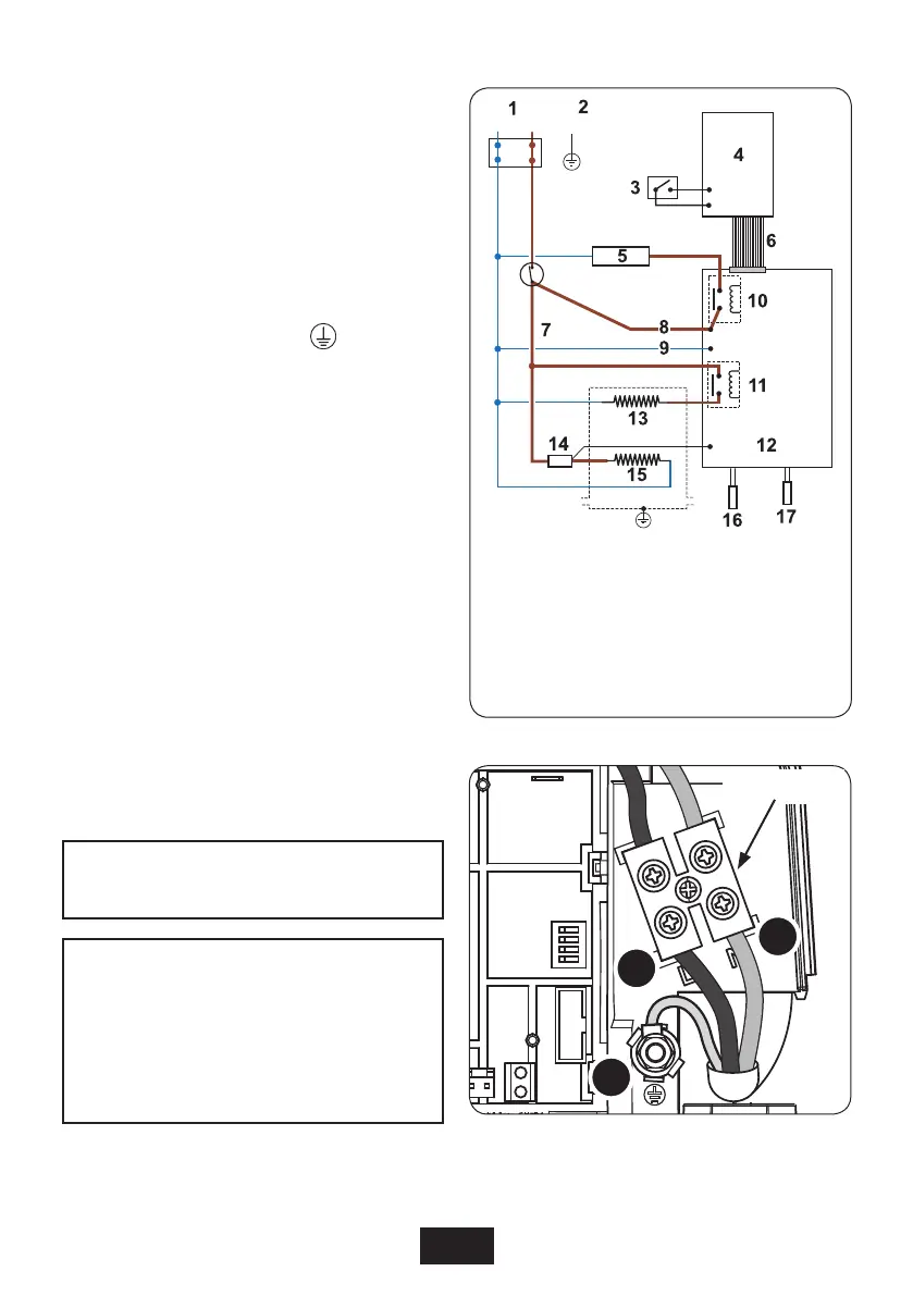
17
SWITCH OFF THE ELECTRICITY SUPPLY AT THE
MAINS.
Fig.12 shows a schematic wiring diagram.
The cable entry points are shown in fig.1. The
cable can be surface clipped, hidden or via
20 mm conduit.
Note: Conduit entry can only be from rear.
Route the cable into the shower unit and connect
to the terminal block (fig.13) as follows:
Earth cable to terminal marked
Neutral cable to terminal marked N
Live cable to terminal marked L
IMPORTANT: Fully tighten the terminal
block screws and make sure that no cable
insulation is trapped under the screws. Loose
connections can result in cable overheating.
Note: The supply cable earth conductor must
be sleeved. The outer sheath of the supply cable
must be stripped back to the minimum.
The supply cable must be secured either by
routing through conduit or in trunking or by
embedding in the wall, in accordance with IEE
regulations.
The use of connections within the unit, or other
points in the shower circuit, to supply power to
unspecified equipment other than that listed on
page12, will invalidate the guarantee.
DO NOT switch on the electricity supply until
the cover has been fitted.
Fig.12
Fig.13
1. Terminal block
2. Earth post
3. Start/stop switch
4. Cover PCB
5. Solenoid
6. 10-way ribbon cable
7. Thermal cut-out
8. PCB live
9. PCB neutral
10. relay
11. relay
12. Power PCB
13. 5.25kW
14. Triac 1
15. 3.25kW
16. Outlet thermistor
17. Low flow switch
N-001-A
Note: The elements on UK models are to 240V
specification and will give a lower kW rating if
the voltage supply is below 240V.
Terminal block
E
L
N
Electrical Connections
WARNING!
After any servicing of mains water
supply, always flush out the
pipework to remove any debris.
In these circumstances the unit should
only be re-started by following the
COMMISSIONING procedure on page 19.

 Loading...