7
Making electrical connections
General safety notes
DANGER!
Danger of electric shock! Do not touch any live com-
ponents! Electrical equipment carries a dangerous
electrical voltage.
– Only skilled qualified electricians are allowed to
work on the electrical system.
– Switch off the power supply before working on
any electrical equipment.
7.1
Connecting the limit switches (fire
dampers with fusible link)
Personnel:
Skilled qualified electrician
3 – 30 V DC
3 – 250 V AC
①
3 – 30 V DC
3 – 250 V AC
①
࿆
࿇
GN
BN
WH
WH
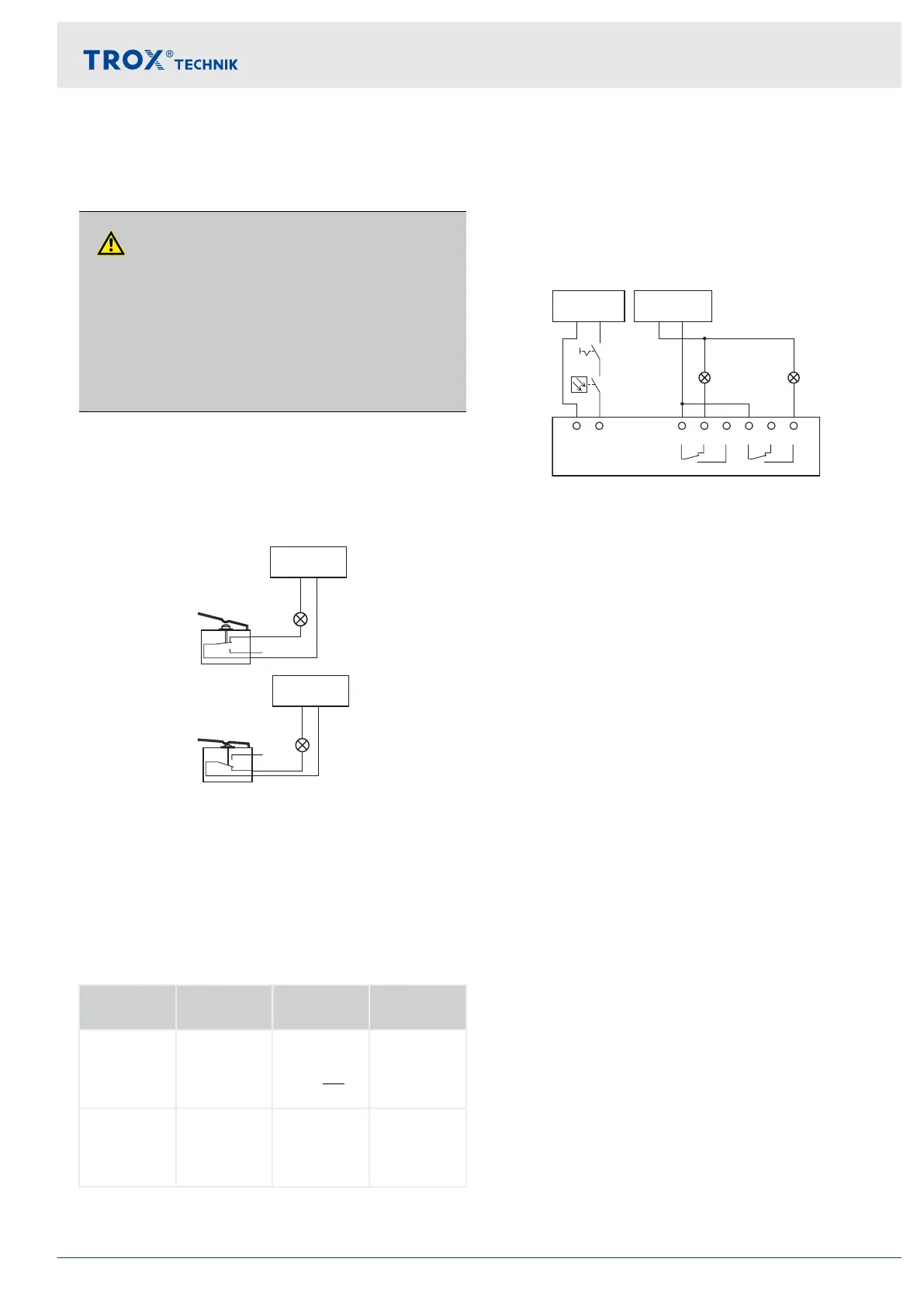
Fig. 38: Wiring example for limit switch
①
Indicator light or relay, to be provided by others
The limit switches must be connected according to
the wiring example Fig. 38
Indicator lights or relays can be connected as long
as the performance specifications are taken into
consideration.
Type of
connection
Limit
switches
Damper
blade
Electric cir-
cuit
Ⓐ NC con-
tact
not actuated CLOSED or
OPEN posi-
tion is not
reached
closed
Ⓑ NO con-
tact
actuated CLOSED or
OPEN posi-
tion is
reached
closed
7.2
Connecting the spring return
actuator
Personnel:
Skilled qualified electrician
230 V AC
24 V
2
L
N(–) L(+)
1
N
S1 S2 S3 S4 S5 S6
<5° <80°
N(–) L(+)
110 – 230 V AC
24 – 48 V DC
①
②
③
④
Fig. 39: Actuator connection, example
①
Switch for opening and closing, to be provided by
others
②
Optional release mechanism, e.g. TROX smoke
detector Type RM-O-3-D or RM-O-VS-D
③
Indicator light for CLOSED position, to be provided
by others
④
Indicator light for OPEN position, to be provided by
others
The fire damper may be equipped with a spring
return actuator for a supply voltage 230 V AC or
24 V AC/DC. Observe the performance data on the
rating plate.
The spring return actuator must be connected
according to the wiring example shown. Several
actuators can be connected in parallel as long as
the performance specifications are taken into con-
sideration.
Actuators with 24 V AC/DC
Safety transformers must be used. The connecting
cables are fitted with plugs. This ensures quick and
easy connection to the TROX AS-i bus system. For con-
nection to the terminals, shorten the connecting cable.
7.3
Equipotential bonding
If equipotential bonding is a requirement, there must be
an electrical earth connection from the fire damper to
the duct. In the event of a fire, mechanical loads from
the equipotential bonding must not affect the fire
damper.
Making electrical connections
Equipotential bonding
Fire damper Type FKRS-EU 51