5.6.1
Mortar-based installation
W
220
W
220
W
220
≥ 100
s = 40 – 60
12,5 12,5
a ≥10
W
Detail Y
40...60
40...60
①
③
④
②
࿆࿇
Y
Y
Y
①
③
②
࿆
࿇
࿆
࿇
①
③
④
②
①
③
④
②
࿆
࿇
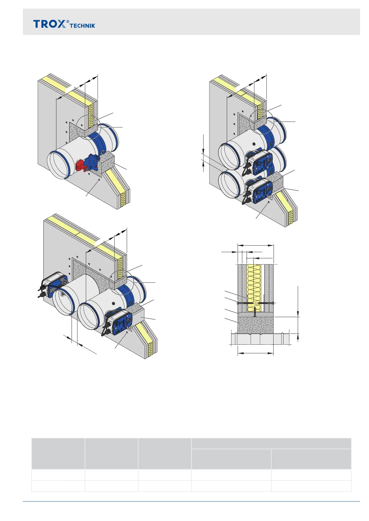
Fig. 17: Mortar-based installation
①
Perimeter metal section
②
Dry wall screw
③
Mortar
④
Trim panels (optional; required for flange-to-flange
installation)
Ⓐ
Installation side
Ⓑ
Operating side
For details on the installation into walls of different thickness see Fig. 18
Performance class and installation details
Performance
class
∅DN [mm] Distance to
load-bearing
structural ele-
ments [mm]
Distance between two fire dampers [mm]
Two installation open-
ings
One installation opening
(flange to flange)
EI 120 S 100...200 ≥75 ≥200 –
EI 90 S 100...315 ≥40 ≥200 40...60
Installation
Lightweight partition walls > Mortar-based installation
Fire damper Type FKRS-EU 29