5.7.1
Mortar-based installation
s
12,512,5
≥100
W ≥ 115
sุ 40
220
□A
□A1
②
③
④
⑤
①
①
࿆࿇
Detail Y
Y
⑤
①
②
①
④
③
࿆
࿇
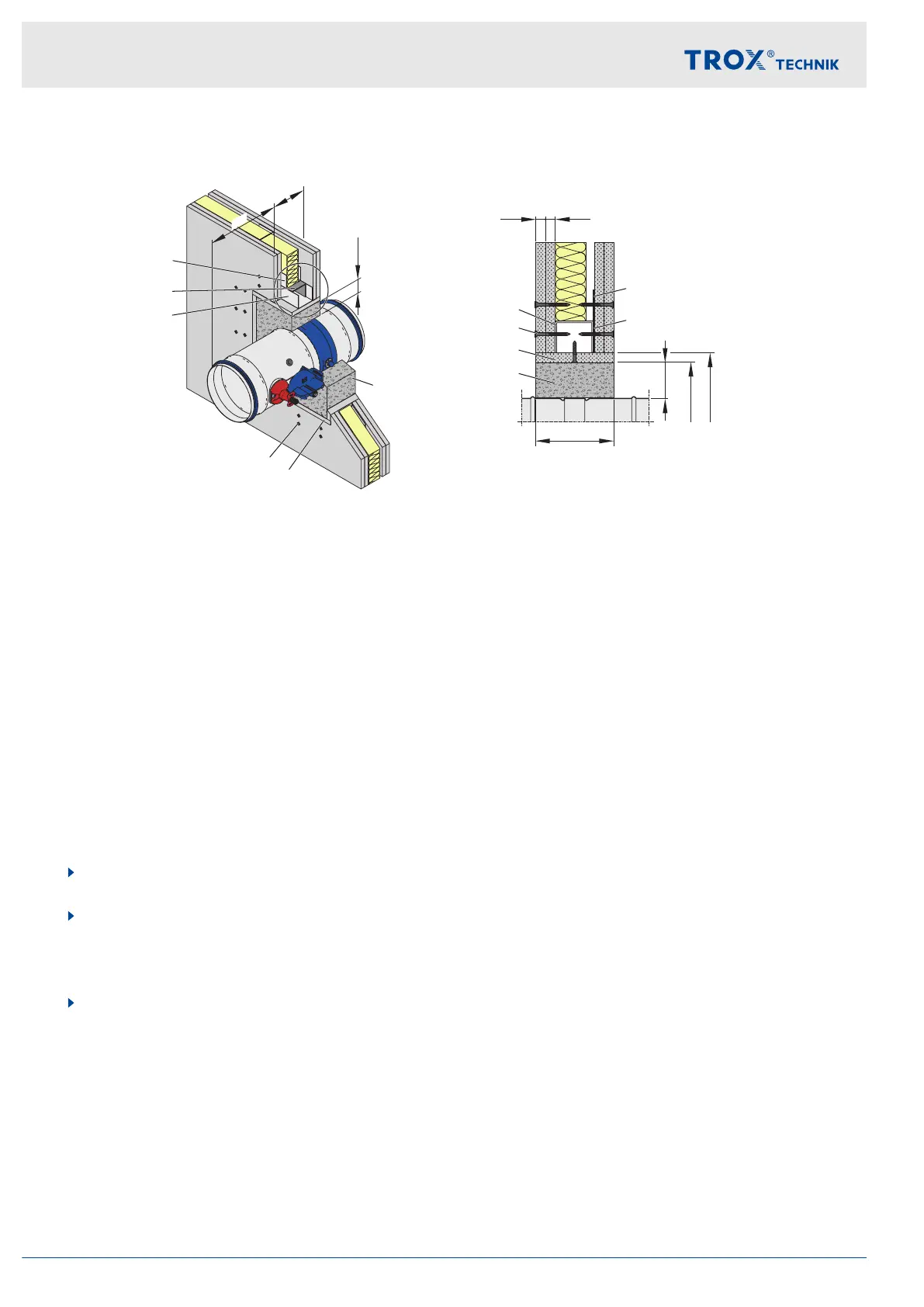
Fig. 26: Mortar-based installation
①
UW section, perimeter
②
UA section, perimeter
③
Dry wall screw
④
Optional trim panels
⑤
Mortar
Ⓐ
Installation side
Ⓑ
Operating side
s = 40 to 60 mm
Personnel:
Specialist personnel
Materials:
Mortar
Ä
‘Acceptable mortars for mortar-based installation’ on page 14
Requirements
Performance class EI 90 S
Fire walls with metal support structure and cladding on both sides, W ≥ 115 mm; detailed specification
Ä
on page 37.
≥ 40 mm distance to load-bearing structural elements
200 mm minimum distance between two fire dampers
Duct connection with flexible connector (recommended)
1. Erect the fire wall according to the manufacturer's instructions and create an installation opening
Ä
on page 37.
2. Push the fire damper into the installation opening and secure it. Make sure that the distance from the con-
necting spigot on the operating side to the wall is 220 mm.
If the wall thickness is >115 mm, extend the fire damper on the installation side with an extension piece or a
spiral duct.
3. Close off the perimeter gap »s« with mortar.
Installation
Fire walls > Mortar-based installation
Fire damper Type FKRS-EU40