5.7
Fire walls
□A
□A1
□A1
≤ 312,5
□A1
C
C
12,5 12,5
a ≥10
W ≥115
C-C
④
⑤
⑤
①
②
③
⑦
⑦
⑥
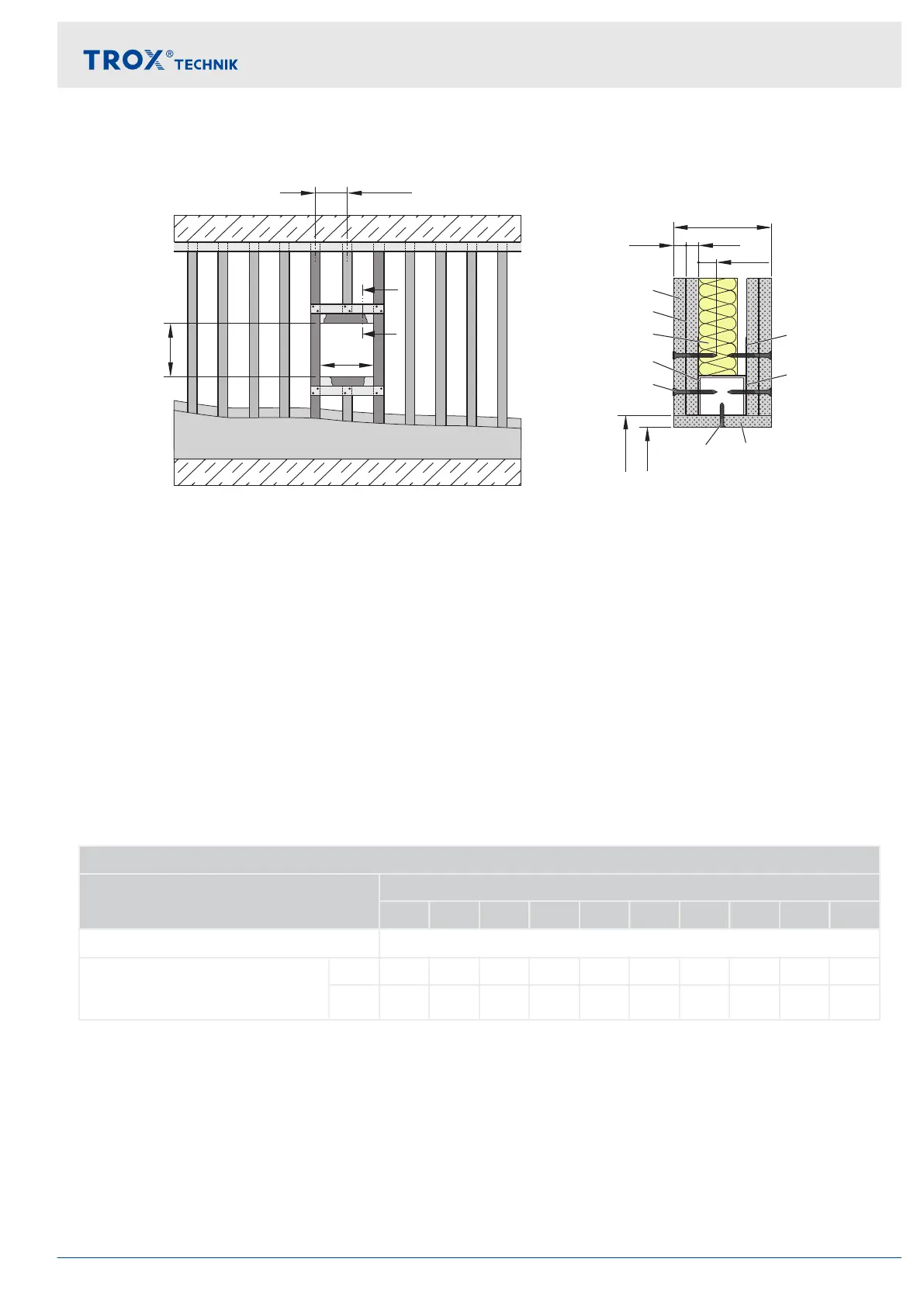
Fig. 23: Fire wall
①
Double layer cladding, on both sides of the metal
stud system
②
Sheet steel insert
③
Mineral wool (depending on wall construction)
④
UA section
⑤
Dry wall screw
⑥
Trim panels (according to the installation details)
⑦
UW section
☐A Installation opening
Requirements
Fire walls with a metal support structure and cladding on both sides, with European classification to EN 13501-2
or equivalent national national classification
Cladding on both sides made of gypsum bonded or cement bonded panel materials or fibre-reinforced gypsum,
wall thickness W ≥ 115 mm
≤ 312.5 mm distance between metal studs
Wall height ≤ 5,000 mm
Sheet steel inserts, additional layers of cladding, or double stud systems are approved
Duct connection with flexible connector (recommended)
Installation opening ☐A [mm]
Installation type Nominal size
100 125 150 160 180 200 224 250 280 315
Mortar-based installation
1
☐A = ∅ DN + (2 x s)
Dry mortarless installation with
square dry mortarless installation
kit TQ
2, 3
☐A 210 235 260 270 290 310 334 360 390 425
☐B1 300 325 350 360 380 400 424 450 480 515
s = 40...60 mm
1)
Optional trim panels
2)
Trim panels are required, ☐A1 = ☐A + 2 x trim panel thickness
3)
Installation opening tolerance +2mm
Installation
Fire walls
Fire damper Type FKRS-EU 37