⑪
⑪
①
③
③
⑩
⑤
①
⑨/⑦
⑧
①
③
⑩
③
①
①
②
⑨/⑦
⑨/⑦
③
①
⑧
⑩
⑤
⑤
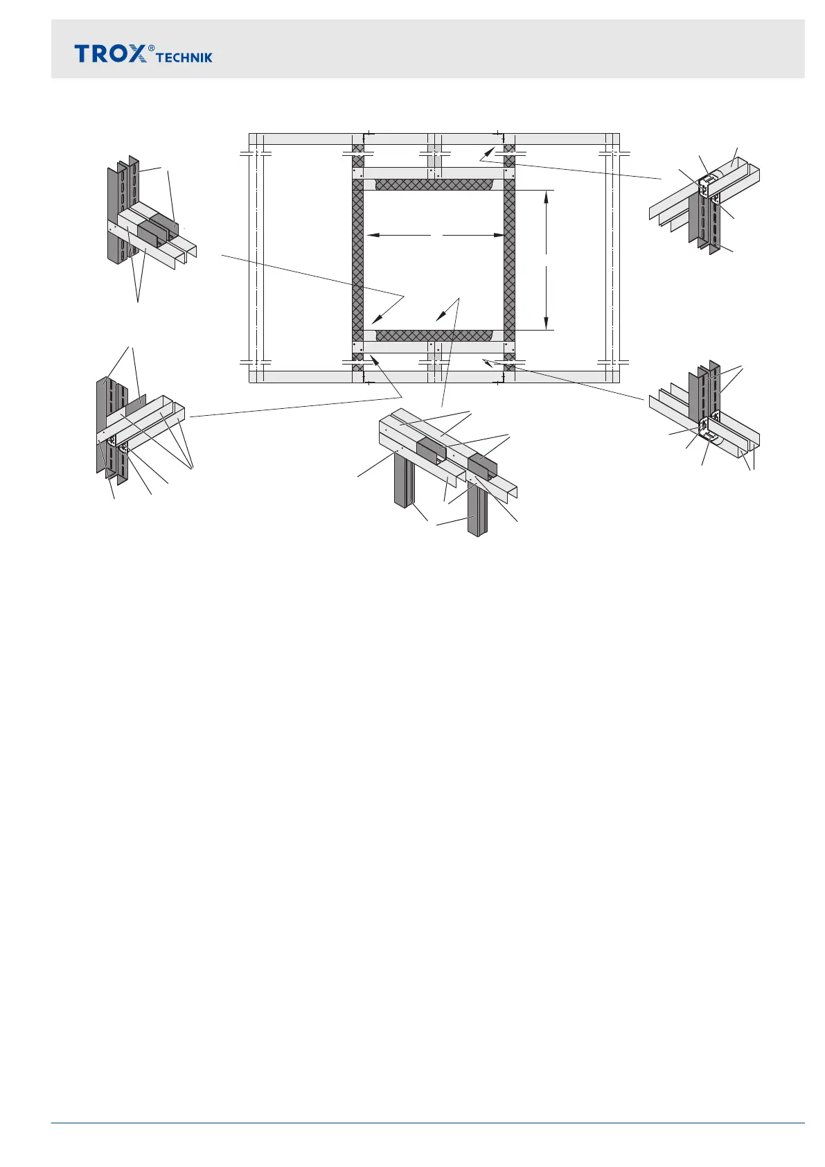
Fig. 25: Double stud system
①
UW section
②
CW section
③
UA section
④
Dry wall screw TB
⑤
Carriage bolt, L ≤ 50 mm, with nut and washer
⑥
Bracket
⑦
Steel rivet Ø 4 mm
⑧
2 × screw, Ø 6 mm, with anchor or hammer-in
fixing
⑨
Dry wall screw Ø 3.9 × 35 mm
⑩
UA connecting bracket; construction elements
according to manufacturer's instructions
⑪
Installation opening depending on installation type
Ä
on page 37
Installation
Fire walls
Fire damper Type FKRS-EU 39