CHAPTER 2: ASSEMBLY INSTRUCTIONS
BIKE ASSEMBLY STEPS (continued):
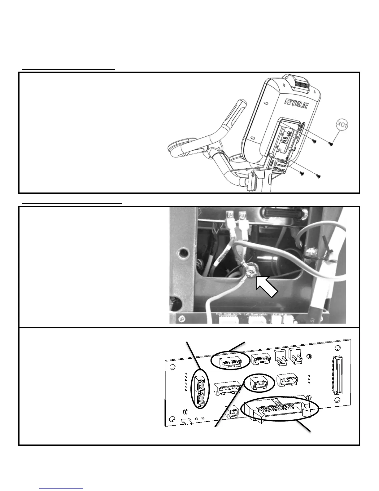
Step 9: Console Mounting:
) The screws used to attach the Console are
p
rovided in the Console packaging
b) Align the back of the Console with the Front
Mast Console Mounting Plate
c
) A
ttach the Console to the Mounting Plate by
tightening all 4 screw with a Phillips head
screwdriver (not provided)
Hardware Required:
*Included with console
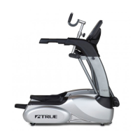
Step 10: Cable Connections :
a) Remove Electronics Board ground wire
screw
b) Re-attach both the Electronics Board ground
wire and the Console ground wire to the Front
Mast Mounting Plate using the same ground
screw.
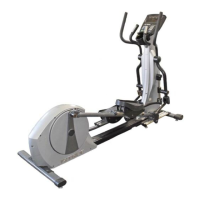
c) Handlebar Cable Connections:
• Telemetry HR (3-pin connector)
• Right Thumb Switch (6-pin connector)
• CHR_(L) & CHR_(R) (3-pin connectors)
It is acceptable to install either cable connector
into either Electronics Board CHR location.
d)
Front Mast Cable Connection:
• 20-pin Connector
Truefitness.com / 800.426.6570 / 636.272.7100 15