28
60020-00216 ∙ 00 ∙ 08/2022
Product description Mover XT4
EN
4 Product description
4.1 Setup
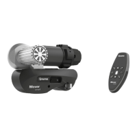
4.1.1 Setup of the entyre system
The manoeuvring system consists of four separate drive
units, each with its own 12V DC motor� These units are
mounted on the frame of the vehicle in the immediate
vicinity of the wheels, and are connected by a lateral
bar�
10
2
1
9
5
6
7
8
3
4
Fig. 1
1 Left drive unit (in the driving direction)
2 Right drive unit (in the driving direction)
3 Right drive unit (in the driving direction)
4 Left drive unit (in the driving direction
5 Remote control
6 Isolating switch
7 Battery
8 Charger
9 Safety socket
10 Remote control
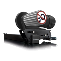
4.1.2 Setup of the drive unit
1 2
3 4
Fig. 2
1 Drive roller
2 Electric motor
3 status display Engaging and disengaging
4 Emergency disengaging mechanism
4.1.3 Setup of the power supply
WARNING
Fire hazard due to the control unit being co-
vered inside the caravan
If the control unit is inadequately ventilated, it
may overheat during operation�
Adequately ventilate the control unit�
Do not cover the control unit�
Drawing serves as an example (Mover XT control
unit)
1 52 3
6
4
Fig. 3
1 Battery
2 Negative terminal
3 Positive terminal
4 Fuse
5 Isolating switch
6 Remote control