60020-00216 ∙ 00 ∙ 08/2022
OperationMover XT4
37EN
Fig. 23
Reverse (turning left):
Fig. 24
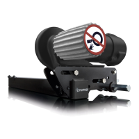
Radio equipment or other remote controls will not
activate your manoeuvring system�
After manoeuvring, apply the parking brake and/or
secure the caravan with chocks to prevent it from
rolling away first of all, then deactivate the mano-
euvring system�
5.5 Coupling to the towing vehicle
The manoeuvring system allows a caravan to be coup-
led to a towing vehicle accurately and without jolting�
However, this requires care and a degree of practice�
Move the towing vehicle close to the caravan�
Secure the towing vehicle against rolling away ac-
cording to the operating instructions�
In order to position the caravan precisely, operate
the control knob or slide control until the caravan’s
coupling is located directly above the ball coupling
on the towing vehicle�
1
2
3
Fig. 25
Coupling the caravan on the ball coupling (Fig. 25-1)
Crank in the jockey wheel and secure it according to
the operating instructions (Fig. 25-2)
Attach the breakaway cable (Fig. 25-3)
Then disengage the manoeuvring system� See
Kapitel 5.6
Insert the 13-pole plug or adapter into the towing
vehicle’s 13-pole supply socket�
5.6 Disengage the manoeuvring system
NOTICE
Property damage due to towing with the
drive rollers engaged
If the caravan is being towed by the towing ve-
hicle with the drive rollers engaged, the mano-
euvring system, the towing vehicle or even the
caravan can be damaged�
Ensure that the drive rollers are completley
disengaged before the caravan is towed by
the towing vehicle�
CAUTION
Personal injury due to the caravan rolling
away
If the drive rollers are disengaged, the caravan
cannot be controlled�
Before the disengagement, apply the
caravan’s parking brake and/or secure the
caravan with wedges�
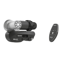
The drive rollers are disengaged on the caravan wheels
by means of the remote control�
To disengage the drive rollers, press and hold both
DISENGAGE buttons at the same time – for
about 3seconds (safety delay) – until you hear
an acoustic signal and the drive rollers start to
disengage�
During the disengagement, the symbol flashes
and the DISENGAGE buttons can be released�
When the drive rollers’ end position is reached, two
acoustic signals sound and the symbol disap-
pears from the toolbar�
Fig. 26
If the disengagement is interrupted, it must be re-
started and performed in full�