38
60020-00216 ∙ 00 ∙ 08/2022
Operation Mover XT4
EN
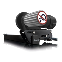
The position indicator shows how far the drive rollers
are engaged or disengaged:
Move r
Fig. 27
1-2
Engagement incomplete
3
Drive rollers completely engaged
No number
visible
Drive rollers completely disengaged
Mover
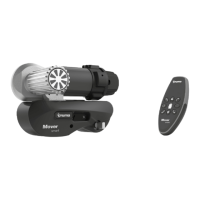
Fig. 28
To check that the disengagement has been successful:
•
In the disengaged position, the drive rollers are ap-
prox� 20mm away from the tyres (Fig. 28) on both
sides� See Kapitel 6�1 to check the correct gap bet-
ween the tyres and drive rollers
•
The position indicator is no longer showing a num-
ber (Fig. 28)�
The manoeuvring system can also be disengaged
manually if the power supply of the manoeuvring
system is interrupted or if a malfunction prevents au-
tomatic disengagement� See Kapitel 5�7 Emergency
disengagement�
5.7 Disengage the manoeuvring
system manually (emergency
disengagement)
CAUTION
Personal injury due to the caravan rolling
away
If the drive rollers are disengaged, the caravan
cannot be controlled�
Before the disengagement, apply the
caravan’s parking brake and secure with
wedges�
NOTICE
Damage due to an incorrect tool
The manoeuvring system must only be disen-
gaged manually� Other auxiliary equipment, e�g�
cordless screwdrivers, can damage the mano-
euvring system�
Use the supplied hexagonal socket spanner�
If the caravan battery is discharged to the extent that
electrical disengagement no longer works or a defect
is present, the drive rollers can also be disengaged
manually�
1
3
2
Fig. 29
Before manual disengagement, apply the caravan’s
parking brake and secure the wheels against rolling
away�
Disconnect the power supply for the manoeuvring
system using the battery cut-off switch�
Prise out the plastic cap (Fig. 29-1) at the rear end of
the cover using a screwdriver�
Insert the hexagonal socket spanner – included in
the scope of delivery – into the hex bolt (Fig. 29-2)
and carefully disengage the drive unit by turning in a
clockwise direction (Fig. 29-3)�
Repeat the procedure for all drive units�