xiv Model 3772/3771 Condensation Particle Counter
APPENDIX C References ....................................................................... C-1
Index
Reader’s Comments Sheet
Figur e s
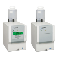
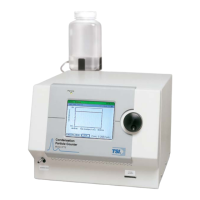
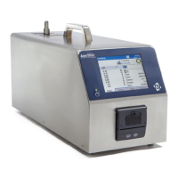
1-1 Model 3772 Condensation Particle Counter ..................................... 1-2
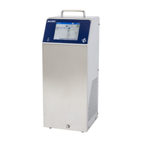
1-2 Model 3771 Condensation Particle Counter ..................................... 1-2
2-1 View of Fill Bottle Bracket Mounting ................................................. 2-3
3-1 View of the Model 3772 Front Panel ................................................. 3-1
3-2 View of the Model 3771 Front Panel ................................................. 3-3
3-3 Back Panel of the Model 3772/3771 CPC ........................................ 3-4
3-4 Sample Digital Pulse from Pulse Output Port at the Back Panel
of the CPC ........................................................................................ 3-6
3-5 Bottom Panel Showing Removable Saturator Base ......................... 3-7
3-6 Internal Components of the Model 3772/3771 CPC ......................... 3-8
3-7 Electronics Boards inside the Model 3772/3771 CPC .................... 3-10
4-1 Model 3772 Display During Warm-Up .............................................. 4-2
4-2 Model 3772 Display After Warm-Up is Completed ........................... 4-2
4-3 Model 3772 Front Panel LCD Display and Keypad .......................... 4-3
4-4 Total Count Mode Data Screen ........................................................ 4-5
4-5 Initial Total Mode Data Screen .......................................................... 4-5
4-6 User Settings Display ........................................................................ 4-5
4-7 Status Display ................................................................................... 4-9
4-8 Status Parameter Display for Diagnostics ........................................ 4-9
4-9 Reformatting the Flash Memory Card ............................................. 4-12
5-1 Flow Schematic of the Model 3772/3771 CPC ................................. 5-6
5-2 Counting Efficiency Curve of 3772/3771 CPC .................................. 5-8
5-3 Response Time of 3772/3771 CPC ................................................ 5-10
7-1 Digi Device Discovery Screen ........................................................... 7-2
7-2 Configure Network Settings Screen .................................................. 7-3
7-3 Digi Connect ME Configuration and Management Screen ............... 7-3
7-4 Main Screen HTML Page .................................................................. 7-4
7-5 RS-232 Connector Pin Designations ................................................ 7-6
8-1 Vacuum Drain Cap Assembly ........................................................... 8-4
8-2 Replacing the Butanol Fill and Drain Filters ...................................... 8-5
8-3 Replacing the Micro Pump Filter ....................................................... 8-6
8-4 Inlet Tube .......................................................................................... 8-7
8-7 O-Rings on Saturator Base (P/N 2501172 and 2501569) ................ 8-9
8-8 O-Rings on Saturator Base (P/N 2500021) ...................................... 8-9
8-9 Connecting SMC Plug to Detector Board ....................................... 8-13
8-10 Typical Analog Pulse Trace ............................................................ 8-13