Installing
14
Hans Turck GmbH & Co. KG | T +49 208 4952-0 | F +49 208 4952-264 | more@turck.com | www.turck.com
5 Installing
The lens curvature does not have to be taken into account for the installation. The sensor de-
tects the object nearest to the sensor and outputs the distance. Object reflections can be
filtered out using the sensor parameters.
The sensors can be installed in any alignment according to application requirements. The radar
wave is propagated perpendicular to the surface of the radar lens. Refer to the following table
for the opening angle:
Type Opening angle
DR…S-… ± 7.5°
The maximum tightening torque for fastening the sensor is 75Nm.
Install the sensor at the intended mounting location. Observe blind zone s
min
, in which no
object detection is possible (see technical data, [}29]).
Install the sensor in such a way that no foreign objects are located in the detection range.
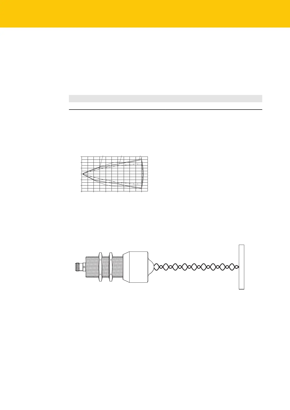
0
-1500
-1000
-500
500
1000
1500
0 3000 6000 9000 12000 15000
mm
Low Gain Standard Gain High Gain
Fig.8: DR…S-… range diagram
Align the sensor at right angles to the desired target. If the radar wave hits the target at
right angles, it will be reflected with the maximum possible signal strength.
Fig.9: Planar target – path of radar waves (schematic)
 Loading...