Setting
Setting and visualizing with the Turck Radar Monitor
26
Hans Turck GmbH & Co. KG | T +49 208 4952-0 | F +49 208 4952-264 | more@turck.com | www.turck.com
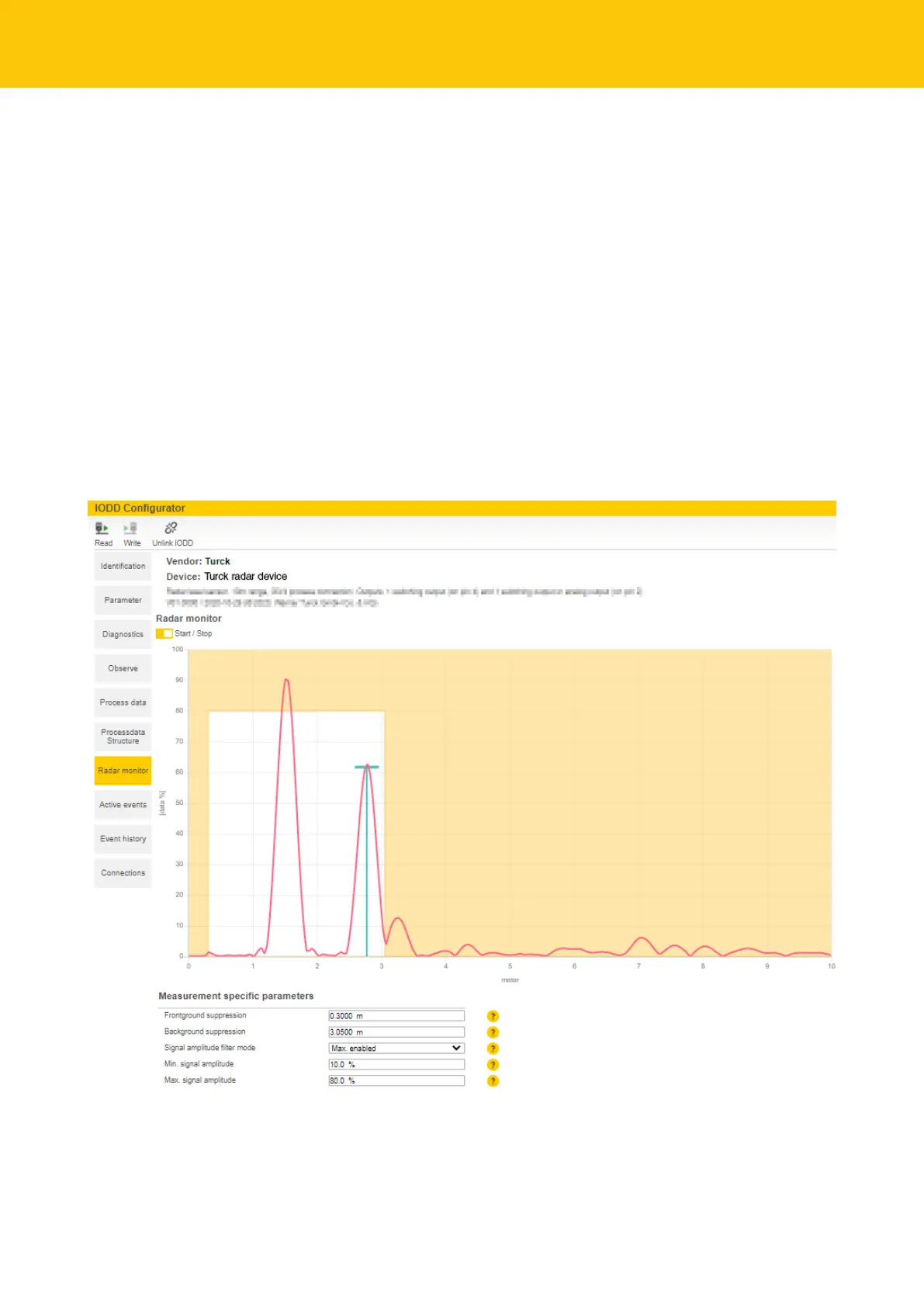
9.3.3 Turck Radar Monitor – filtering signals
The Turck Radar Monitor offers four filter options for suppressing interference signals:
n Foreground suppression (≥ 0.3 m)
n Background suppression (≤ max. range + 0.05 m)
n Min. signal intensity filter
n Max. signal intensity filter (≥ 10%)
The minimum distance between foreground and background suppression is 0.1m. Example: If
the foreground suppression is set to 1 m, the background suppression must be ≤ 0.9m or
≥1.1m.
Minimum and maximum signal intensity filters can be activated individually or together. The
step width is 1%. The minimum distance between the minimum and maximum signal intensity
filter is 10 %.
Only peaks within the signal limits are passed on for further processing.
Adjust the filter in the Measurement specific parameters area.
a The signal limits are indicated in the Turck Radar Monitor in a white area. Peaks without
blue bars are not passed on for data processing.
Fig.23: Example – filtering signals
 Loading...