Setting
Setting by manual bridging (shorting)
20
Hans Turck GmbH & Co. KG | T +49 208 4952-0 | F +49 208 4952-264 | more@turck.com | www.turck.com
9.1.3 Setting the switching window
Run Mode
Success:
LED GN 2 s
Fail:
LED YE 2 s, 5 Hz
Out 1: 2…8 s
LED GN 1 Hz
Position object
for SP 1
Set SP 1: 2…8 s
LED YE 1 Hz
Out 2: 8…14 s
LED GN 2 Hz
Position object
for SP 1
Set SP 1: 2…8 s
LED YE 1 Hz
Abort: > 20 s
LED GN/YE
2 s, 5 Hz
Abort: > 20 s
LED GN/YE
2 s, 5 Hz
Success:
LED GN 2 s
Fail:
LED YE 2 s, 5 Hz
Out 1: 2…8 s
LED GN 1 Hz
Position object
for SP 2
Set SP 2: 8…14 s
LED YE 2 Hz
Out 2: 8…14 s
LED GN 2 Hz
Position object
for SP 2
Set SP 2: 8…14 s
LED YE 2 Hz
Abort: > 20 s
LED GN/YE
2 s, 5 Hz
Abort: > 20 s
LED GN/YE
2 s, 5 Hz
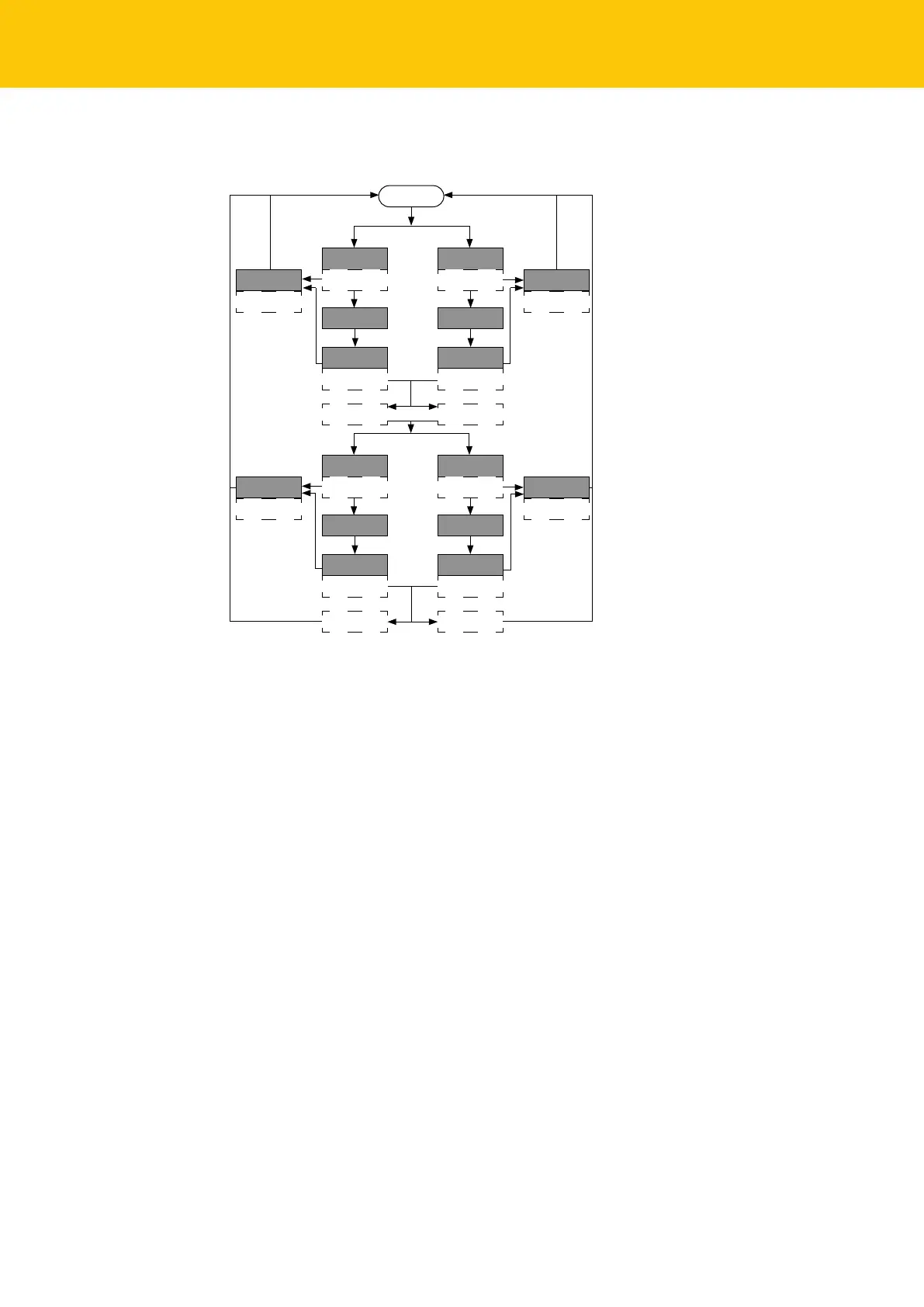
Fig.17: Flow chart
The device is in Window mode if a switch window was selected. SP1 and SP2 are defined by the
user. The sensor operates as a retroreflective sensor around SP1 if the hystereses of SP1 and SP2
overlap.
Select the output.
Position the object for switch point 1 in the detection range.
Short circuit Pin 1 and Pin 4 within 30 s for 2…8 s.
a Switching point 1 was successfully set if the LED flashes green for 2 s.
Reselect the output.
Position the object for switch point 2 in the detection range.
Short circuit Pin 1 and Pin 4 within 30 s for 8…14 s.
a Switch 2 point was successfully set if the LED flashes green for 2 s.
 Loading...