Connection
Wiring diagrams
16
Hans Turck GmbH & Co. KG | T +49 208 4952-0 | F +49 208 4952-264 | more@turck.com | www.turck.com
6 Connection
NOTE
The device must be provided with an SELV/PELV power supply compliant with a lim-
ited energy circuit in accordance with UL61010-1 3rd Edition (IEC/EN 61010-1).
Connect the female connector of the connection cable to the male connector of the
sensor.
Connect the open end of the connection cable to the power supply and/or processing
units.
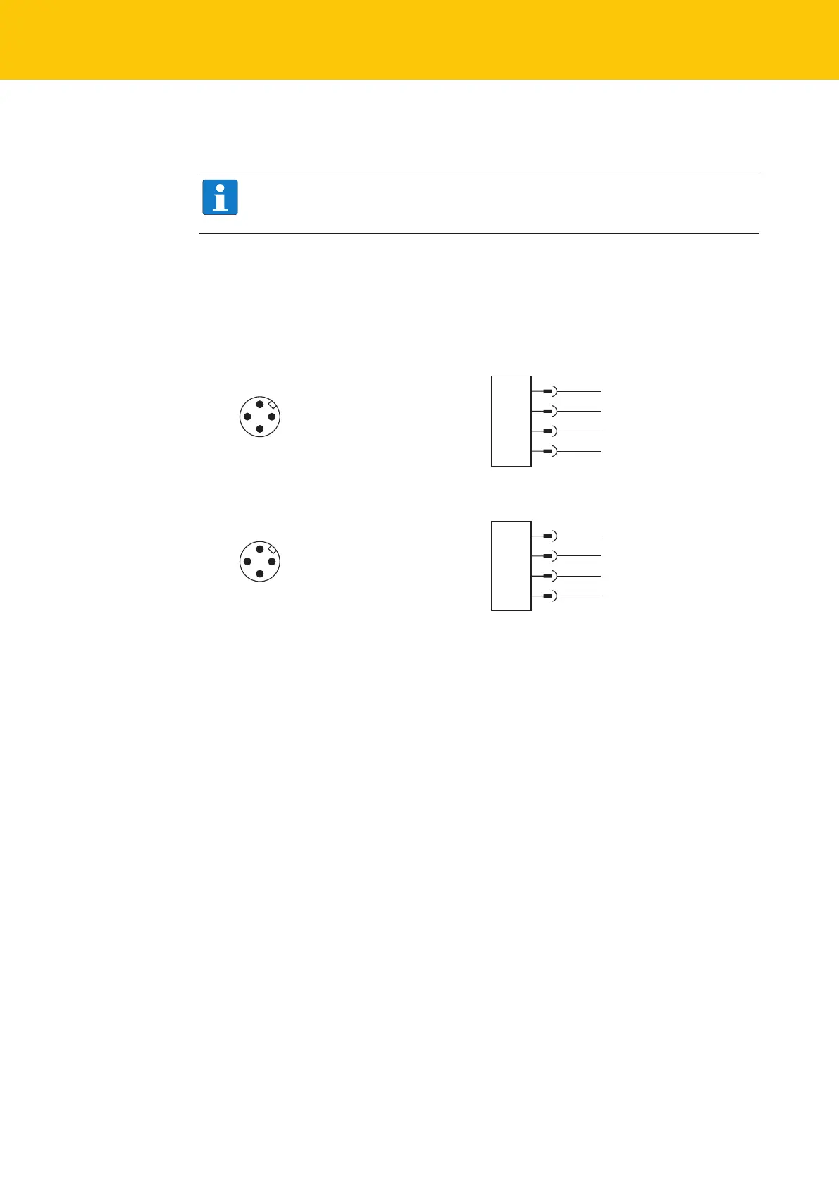
6.1 Wiring diagrams
1
4
2
3
+
–
out 2: switch / analog
out 1: switch / IO-Link
Fig.12: DR…IOL8X2 pin layout Fig.13: DR…IOL8X2 wiring diagram
1
4
2
3
+
–
out 2: switch
out 1: switch / IO-Link
Fig.14: DR…2UPN… pin layout Fig.15: DR…2UPN… wiring diagram
 Loading...