V01.00 | 2021/11
21
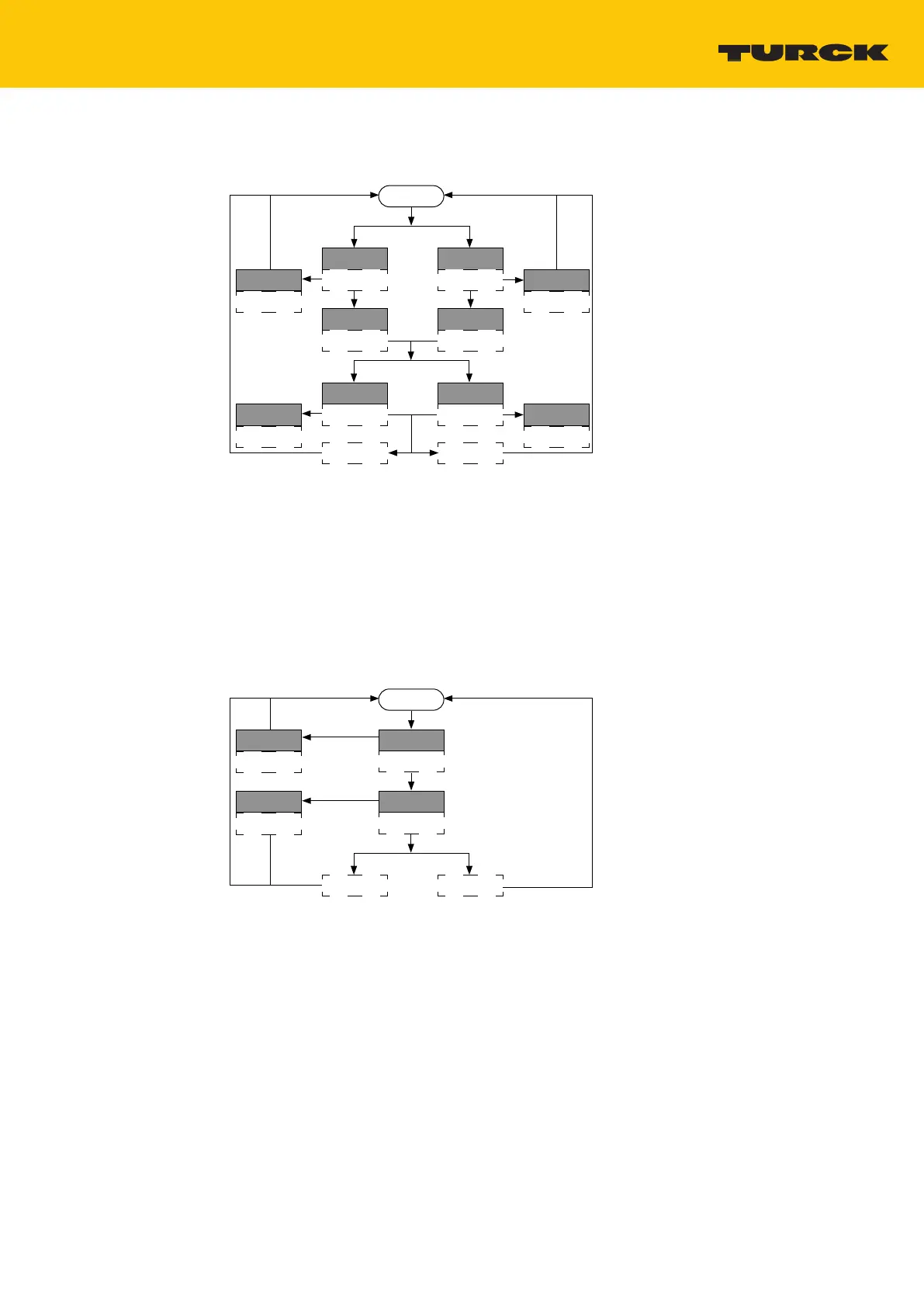
9.1.4 Setting the output function
Run Mode
Out 1: 2…8 s
LED GN 1 Hz
Prepare:
14…20 s
LED YE 4 Hz
Out 2: 8…14 s
LED YE 1 Hz
Prepare:
14…20 s
LED YE 4 Hz
Abort: > 20 s
LED GN/YE
2 s, 5 Hz
Abort: > 20 s
LED GN/YE
2 s, 5 Hz
Success:
LED GN 2 s
Fail:
LED YE 2 s, 5 Hz
PNP:
2…8 s
LED GN/YE 1 Hz
NPN:
8…14 s
LED GN/YE 2 Hz Abort: > 20 s
LED GN/YE
2 s, 5 Hz
Abort: > 20 s
LED GN/YE
2 s, 5 Hz
Fig.18: Flow chart
Select the output.
Short circuit Pin 1 and Pin 4 within 30 s for 14…20 s.
PNP output: Short circuit Pin 1 and Pin 4 for 2…8 s.
NPN output: Short circuit Pin 1 and Pin 4 for 8…14 s.
a The output function was successfully set if the LED flashes green for 2 s.
9.1.5 Resetting to factory settings
Run Mode
Prepare:
14…20 s
LED GN 4 Hz
Reset: 2…8 s
LED YE 1 Hz
Abort: > 20 s
LED GN/YE
2 s, 5 Hz
Success:
LED GN 2 s
Fail:
LED YE 2 s, 5 Hz
Abort: > 8 s
LED GN/YE
2 s, 5 Hz
Fig.19: Flow chart
Start reset: Short circuit Pin 1 and Pin 4 for 14…20 s.
Press Reset: Short circuit Pin 1 and Pin 4 within 30 s for 2…8 s.
a The device was successfully reset if the LED flashes green for 2 s.
 Loading...