Product Description
Functions and operating modes
10
Hans Turck GmbH & Co. KG | T +49 208 4952-0 | F +49 208 4952-264 | more@turck.com | www.turck.com
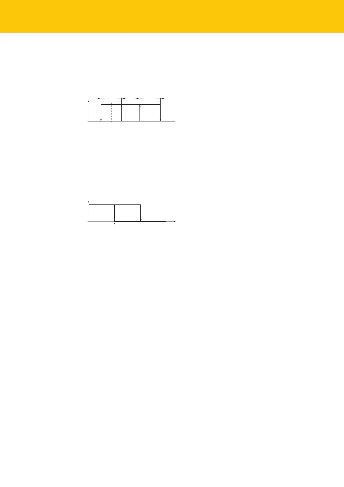
Digital output– window mode
In Window mode the start and end point of the switching window can be set for the digital
output either via IO-Link (indices 0x3C and 0x3E) or with an available target. The switch window
must be within the detection range. The hysteresis can be set.
Fig.3: Window mode
Digital output– two point mode
In Two point mode one switch-on point and switch-off point can be set for the digital output
either via IO-Link (indices 0x3C and 0x3E) or with an available target. The mode can also be
used for a freely adjustable hysteresis.
Fig.4: Two point mode
4.4.3 Output functions – analog output
The analog output of the DR…IOL8X2 sensors can be set as either a current or voltage output.
The measuring range is freely definable.
The minimum distance between the start and end point is 500 mm.
Current output
In the defined measuring range, the device supplies an analog current signal between ASP
(analog start point) and AEP (analog end point). The following output configurations can be set:
n 4…20 mA (factory setting)
n 0…20 mA
n 20…4 mA
n 20…0 mA
 Loading...