V01.00 | 2021/11
19
9 Setting and Parameterization
Teach in the devices as follows:
n Manual bridging (shorting): Short circuit pin 1 with pin4.
Once the teach-in process has been successfully completed, the devices automatically switch
to normal operation.
The LED is lit green for 2 s if the teach-in operation is successful. If a teach-in operation was not
successful, the LED flashes yellow for 2 s at a frequency of 5Hz.
9.1 Setting by manual bridging (shorting)
9.1.1 Selecting the output
Switching output 1: Short circuit Pin 1 and Pin 4 for 2…8 s.
Output 2: Short circuit Pin 1 and Pin 4 for 8…14 s.
a The output was successfully selected if the LED flashes green for 2 s.
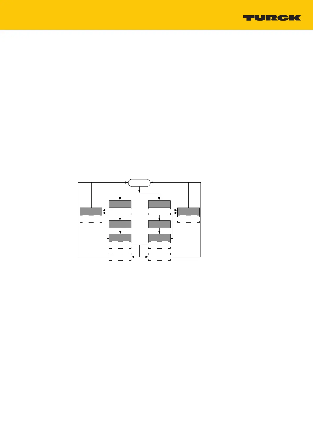
9.1.2 Setting a single switch point
Run Mode
Success:
LED GN 2 s
Fail:
LED YE 2 s, 5 Hz
Out 1: 2…8 s
LED GN 1 Hz
Position object
for SP
Set SP: 2…8 s
LED YE 1 Hz
Out 2: 8…14 s
LED GN 2 Hz
Position object
for SP
Set SP: 2…8 s
LED YE 1 Hz
Abort: > 20 s
LED GN/YE
2 s, 5 Hz
Abort: > 20 s
LED GN/YE
2 s, 5 Hz
Fig.16: Flow chart
If a single switch point is set, the device behaves as in Window mode. Besides the set switch
point, a virtual switch point is present at the beginning of the detection range.
Select the output.
Position the object for the switch point in the detection range.
Press Pin 1 and Pin 4 to U
B
within 30 s for 2…8 s.
a The switching point was successfully set if the LED flashes green for 2 s.
 Loading...