Do you have a question about the twintex LCR Series and is the answer not in the manual?
Explains safety symbols used in the manual and on the LCR meter.
Provides essential guidelines for safe operation, handling, and environment.
Overview of the LCR series, its accuracy, display, and applications.
Lists key features like processor, display, interfaces, and memory capabilities.
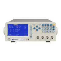
Introduces the LCR meter's front panel, detailing its components and controls.
Details front panel elements like power switch, USB host, terminals, LCD, soft keys, and cursor keys.
Describes front panel indicators (PASS/FAIL), menu, setup, system, file, trig, ESC, backspace, OK, and number keys.
Details the connectors and layout of the LCR meter's rear panel.
Explains how to display measurement parameters on screen.
Details selecting measurement range modes and test frequencies.
Explains how to set test speed and test level voltage.
Covers setting comparator ON/OFF and adjusting parameter display.
Details the BIN DISPLAY function for sorting measurements into bins.
Covers setup of measurement parameters like ResSource, AVERAGE, etc.
Covers system settings like Theme, Language, Password, etc.
Details communication setup for Bus Mode, BaudRate, etc.
Displays model number, firmware version, hardware version.
Explains how to store measurement data to a USB flash stick.
Describes viewing and managing internal/external parameter files.
Outlines steps for reading, saving, uploading, and copying parameter files.
Lists effective measurement ranges for 100Ω and 30Ω source resistance.
Details accuracy calculations for |Z|, L, C, R, X.
Provides accuracy formulas for Q, θ, Rp, and Rs.
Details the pin assignments and signals for the HANDLER interface.
Explains the time sequence chart for the HANDLER interface signals.
Provides a schematic diagram of the HANDLER interface signal connections.
Describes the RS232C interface, its minimal subset, and connection illustration.
Explains how to use the USB HOST for controlling the LCR meter via USBTMC.
Guidelines for inspecting the LCR meter to maintain performance and check for damage.
Step-by-step instructions for replacing the fuse, including rating information.
Summarizes measurement functions, parameters, frequencies, and accuracy for different models.
Lists measurement ranges and units for parameters like |Z|, Y, C, L, D, Q, θ.
Details comparator, memory, standard interfaces, operating environment, power, and dimensions.
Introduces the manual's purpose: writing commands for remote control.
Describes GPIB common commands: *RST, *IDN?, *TRG, FETC?, *SAV, *RCL.
Explains SCPI command structure, parameters, and various command categories.
Details data output formats and string formats for SCPI commands.
| Measurement Parameters | L, C, R, Q, D |
|---|---|
| Test Frequency | 100Hz, 120Hz, 1kHz |
| Display Range L | 0.0001μH to 9999H |
| Display Range C | 0.0001pF to 9999μF |
| Display Range R | 0.0001 Ω - 99.99 MΩ |
| Power Supply | AC adapter |