22
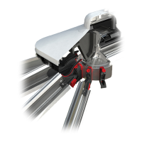
SPEEDLOCK REMOVAL
SECTION 5
Gently pulling the bar away will automatically
release the head of the speedlok.
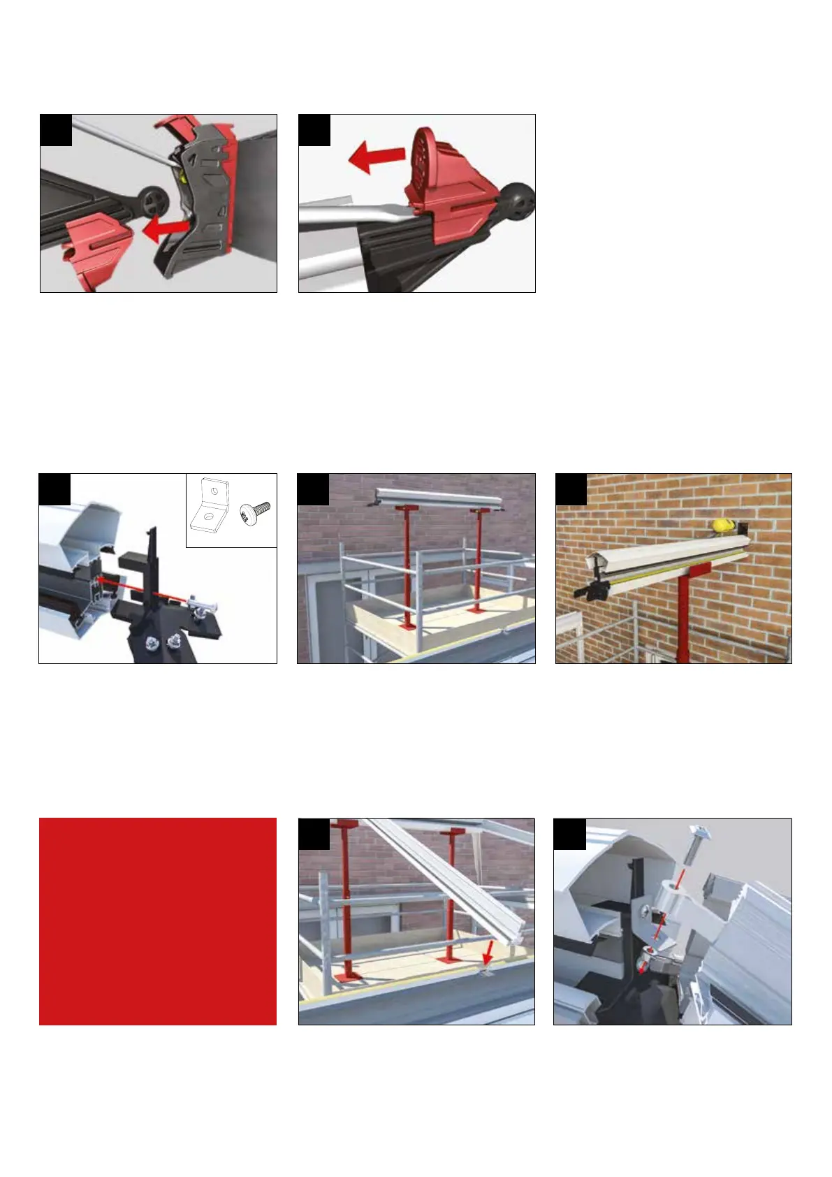
4
Turn the whole bar over, then insert the
screwdriver blade under the lower wedge
lock. Lift to allow the wedge to ride back
over the serations to its original position.
5
SLIMLINE RIDGE
SECTION 6
Prop ridge in position using suitable supports,
centralising between eaves beam sections.
(When the ridge features aluminium painted
internal nish it will need to be protected whilst
supporting).
Using the roof rise height supplied set the ridge
and x the bracket to the host wall using the
appropriate xings.
LANRF001 (xing screw) is supplied pre-
installed into the ridge. Remove and x radius
end (LAN032BL) then replace the screw. If using
3 bar attach LAN031 using EBT001. (M5x12
P021 pan screw).
LAN031 EBT001
Depending upon the roof size and options requested, t hub end transom bar and / or side transom
bars. If specied on the job, remove nuts from bolts in transom position and t transom bar over
bolts. Re t nuts and hand tighten. Check that ridge is level and fully tighten nuts on all bars.
When a transom is tted between hips, lift
transom bar sleeved spigot over bolt, then
tighten nut.
TRANSOM BARS
- If your project
has them
1 2 3
4 5
 Loading...