44
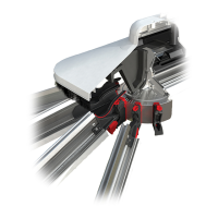
Now attach the Inter-Rafter
weathering hood (may require
trimming in certain situations).
3
Lift the‘ap’onleadingedgeof
the weathering hood, slide the
sealed unit underneath and push
apbackintoposition.
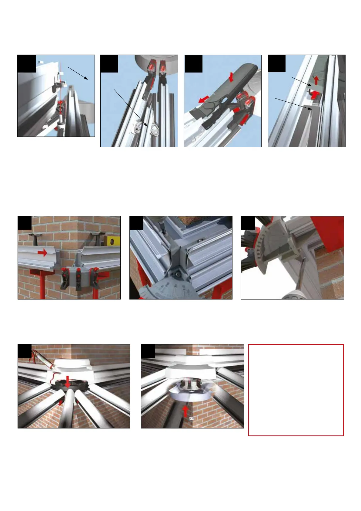
Using the main installation guide,
build the roof as normal. Attach
the bars to hub end as normal
(steps 11-13 installation guide
p9). Insert the Inter-Rafter into
its position between the 2 pre-
preparedbarsanddropthe‘eye’
over the threaded post.
1
Bolt down using the nuts
provided - ensure glazing
platforms are level.
2
Inter-Rafter
Inter-Rafter
INTER RAFTER
SECTION 21
FITTERS TIP - Radius end top
cap
- Plan for access
- Leave a panel out to enable
access for tting the top
cap.
- Temporarily pack the
glazing bar top caps as
required where panel has
been removed
L SHAPE RIDGES - HALF RIDGE TO HALF RIDGE
Take the 2 pieces of half ridge and oer
intonalposition.Supportusingadjustable
support prop, taking account of all H&S
issues. Check levels. One half ridge already
has the radius assembly attached.
1 2 3
Now build the remainder of the roof in sequence. Then,
as in step 52, p16, seal around each glazing bar top cap
whereitmeetstheinnerwallofthe‘softtouch’weather-
ingshield.Trialtthehalfridgeexternalradiusendtop
capintoposition. Mark and drill fornal rivetpositions
usinga5mmdrillbit.Trimtot(seepage40).Whensat-
isedwitht,applyabeadofappropriatesealantacross
each end of the half ridge top cap. Place the radius end
cover over the weathering shield and rivet into position.
4
Trialttheinternalradiusendcover
into position. Minor trimming to
ensure a snug t may be required.
Oerintopositionandsecureusing
the threaded plastic rose.
5
On the top shelf of the half ridge, x the
bracket using one M6 x 25mm taptite
(pozidrive) screw.
On the underside of the half ridge, fasten
the bracket using 2 M5 x 12mm taptite
screws. Check the L shaped half ridge is
nallylevelandattachtothehostwallusing
masonry anchors appropriate to substrate.
SECTION 22
Flap
Sealed
Unit
4