35
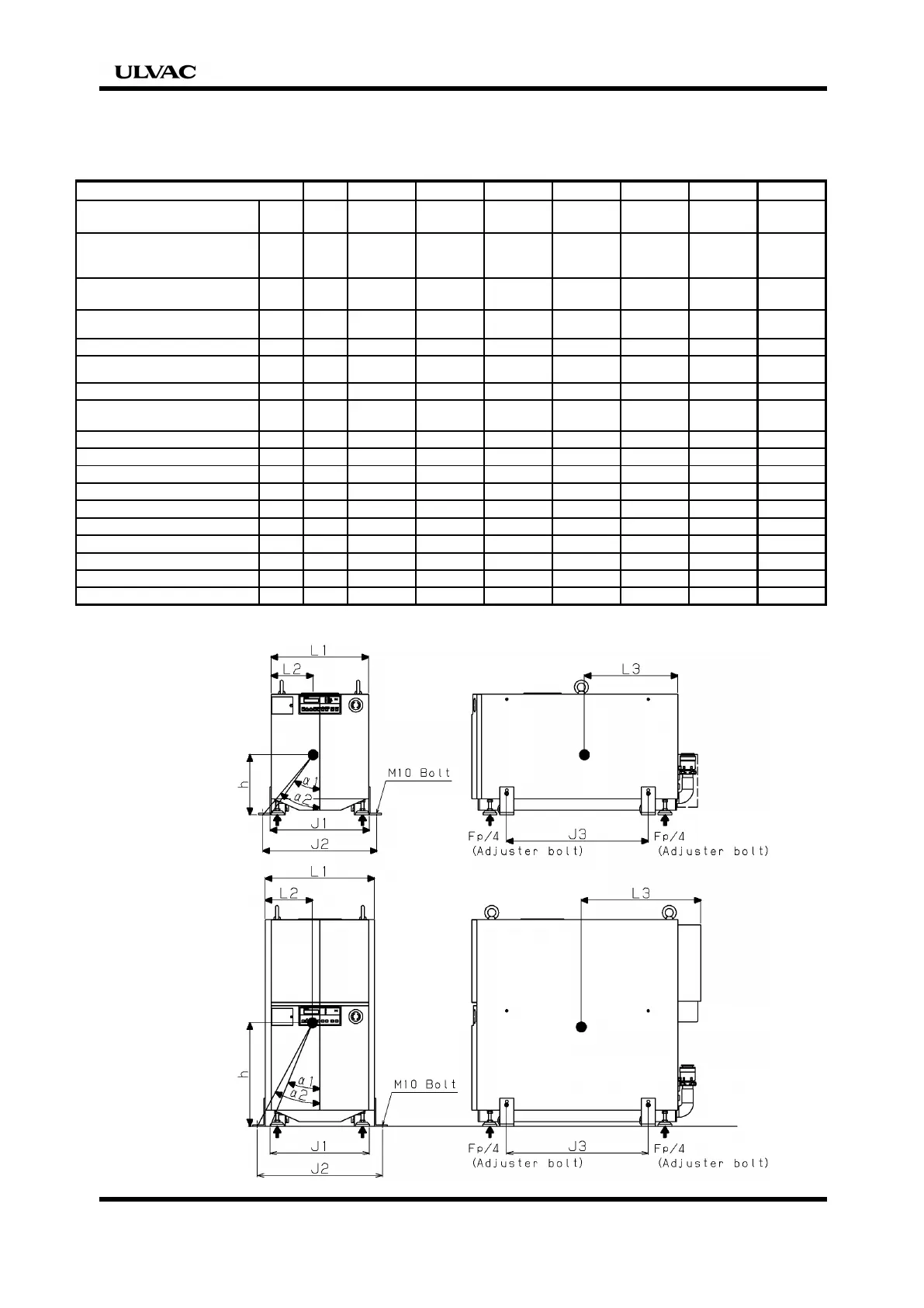
Antiearthquake procedures
unit LR/HR60 LR/HR90 LR/HR180 LR/HR300 LR/HR600 LR/HR1200 LR/HR1800
The maximum width on surface of
projection which falls easily
L1 mm 370 420 520 378 470 470 520
Short distance from fulcrum on surface
of projection which falls easily to
center of gravity position
L2 mm 161 180 222 161 205 200 223
The distance from rear panel to center
of gravity position
L3 mm 383 403 465 491 529 517 661
Height from floor side to center of
h mm 242 258 307 445 488 580 606
Weight of device
Wp kg 180 245 335 275 370 420 545
Horizontal pressure(Adjuster)
Fp/4 kg 42.3 57.6 78.7 64.6 87.0 98.7 128.1
0.94*h>=0.85*L2
OK OK OK OK OK OK OK
Fall power
R=(Wp*(0.94h-0.85L2))/(2*L1)
R kg 22.0 26.1 32.2 102.4 111.9 167.6 199.3
Shearing power of anchor bolt (M10)
τ
1537 1537 1537 1537 1537 1537 1537
Fp<
τ
OK OK OK OK OK OK OK
Tensility of anchor bolt(M10)
σ
2300 2300 2300 2300 2300 2300 2300
R<
σ
OK OK OK OK OK OK OK
Jack interval
J1 mm 378 428 528 378 428 428 528
Earthquake-proof Bracket interval
J3 mm 556 610 655 556 610 610 655
Fall angle
α
1 deg 38.0 39.7 40.7 23.0 23.7 20.3 23.5
Earthquake-proof Bracket interval
J2 mm 440 490 590 440 540 540 590
Fall angle
α
2 deg 42.3 43.5 43.9 26.3 29.0 25.0 25.9
α
>15deg OK OK OK OK OK OK OK
ULVAC, Inc. Components Div.
Date : November 25, 2002
300/600/1200/1800
60/90/180
 Loading...