2
1.1 Overall Configuration
1.1.1 Pump Structure
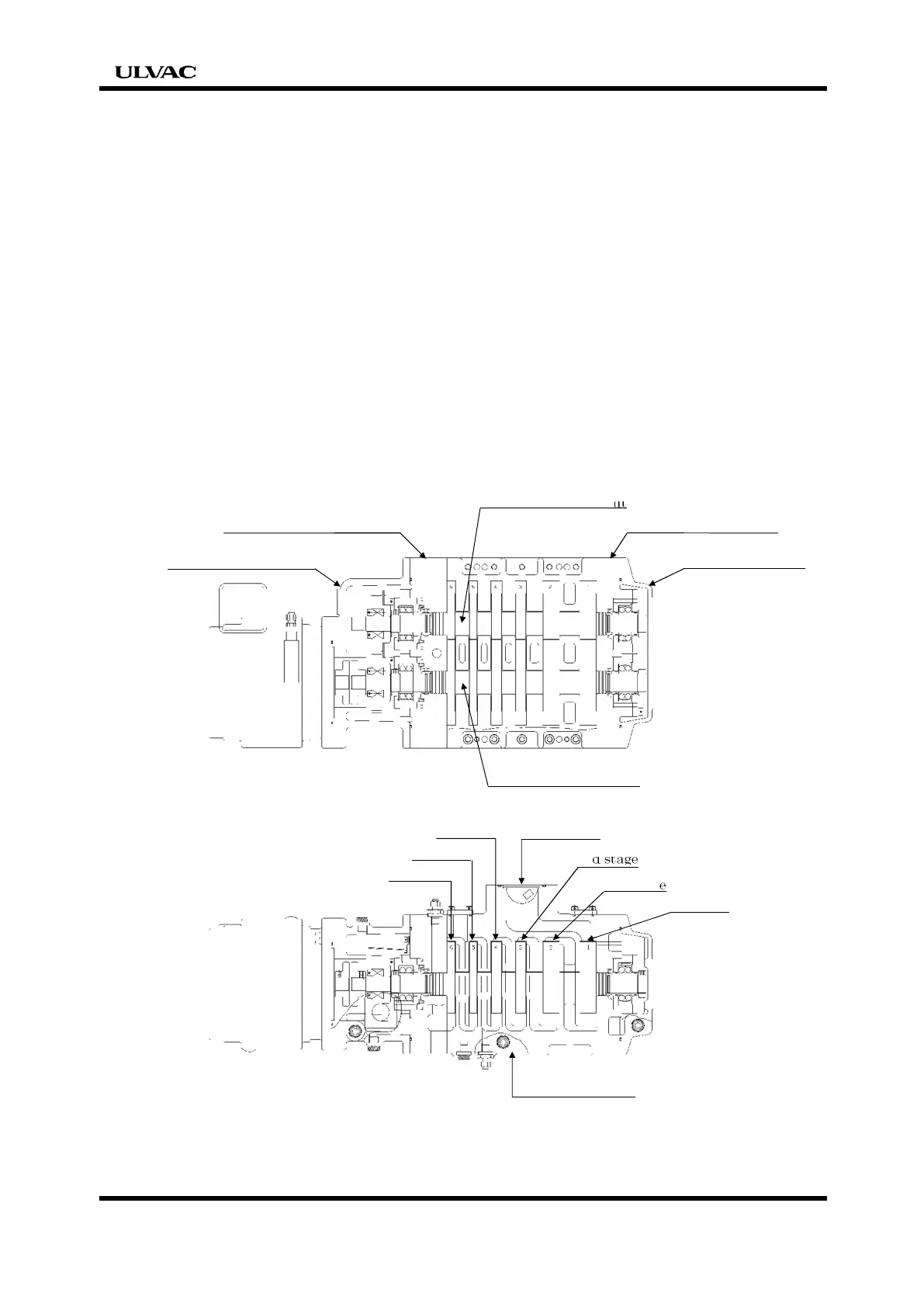
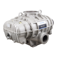
As for a primary pump, the root rotor of six pairs queues up in the series. Casing
space is gradually reduced toward the outlet. The booster pump is composed of the
root rotor of big capacity by one stage.
The two rotors are positioned with a small allowance gap and rotate in opposite
directions without contact with each other. Gases is introduced from the top of
casing and pass through toward the bottom of it, then spew out from the outlet
port.
The aluminum alloy casting is used for the main parts which compose the pump.
And the aluminum surface is treated with a special process.
Canned motor is used to drive the rotors. This can eliminate the shaft seal
construction, this improved the reliability of the device.
Vacuum-side side cover
Vacuum-side cover
Driving-side rotor shaft
6th stage
4th stage
2nd stage
Top cylinder


 To Next Page