19
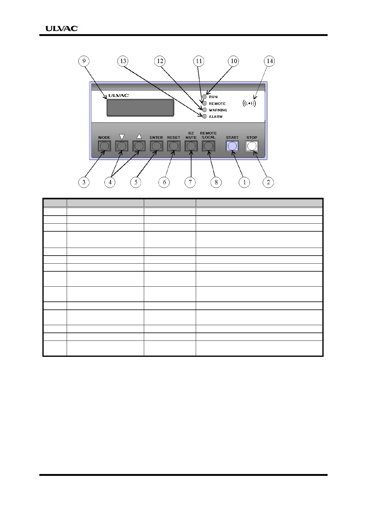
1.4 Description of Controller
No. Control Sign Function
1 START switch START Starts the pump.
2 STOP switch STOP Stops the pump.
3 MODE switch MODE Selects a setting item.
4 Input change switch
▽
△
Changes over the set value.
Changes the selected content of setting.
5 ENTER switch ENTER Determines the selected item and setting.
6 RESET switch RESET Resets the alarm.
7 BZ MUTE switch BZ MUTE Stops buzzer sound.
8
REMOTE/LOCAL
switch
REMOTE
/ LOCAL
Changes over the REMOTE/LOCAL mode.
9 Display LCD
Displays the current status with
characters.
10 RUN lamp LED1 (green) The lamp lights when the pump starts.
11 REMOTE lamp LED2 (green)
The lamp lights when the pump is running
in the REMOTE mode.
12 WARNING lamp LED3 (orange)
The lamp lights when WARNING is given.
13 ALARM lamp LED4 (red) The lamp lights when ALARM is given.
14 Buzzer BZ
The buzzer sounds in case of WARNING or
ALARM.
When any trouble occurs, LED3 (orange:No12) and LED4 (red:No13) on the controller will
light and warning buzzer sounds. Detailed information will be indicated on the LCD


 To Next Page