42
- Before start the work, ensure that all hazardous energies are shutoff. Refer to the
Section 2.1 For safety Use.
- Wiring work should be performed by licensed worker.
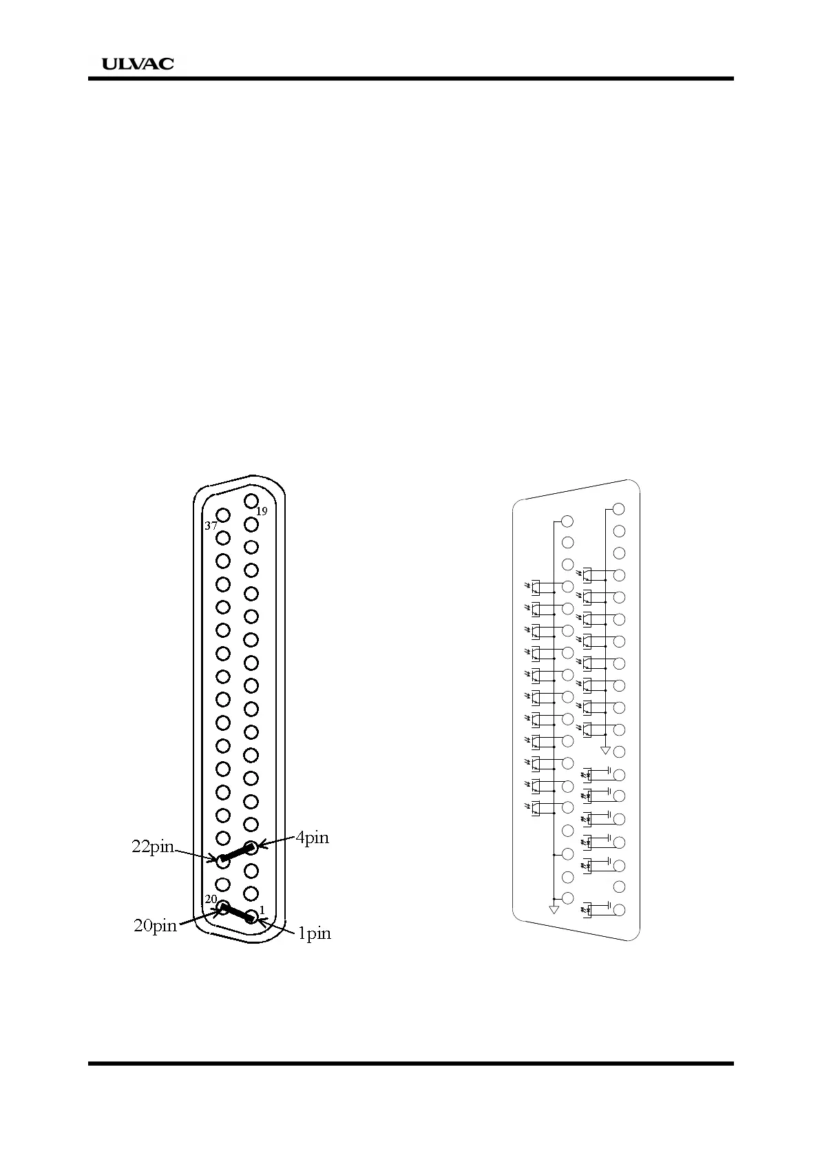
- If the external interlock function is not used (used when an interlock with
equipment other than a system in which the pump is installed is activated),
connect 1 and 20 by a jumper wire or if the remote emergency stops function (only
AC line is shut down) is not used, connect 4 and 22 by a jumper wire. If this wiring
is not connected between these pins, the pump will recognize it as an external
interlock command or an emergency shutdown command and will not start. (Refer
to Fig.1)
- A voltage of 24VDC is applied to the input system on the pump side. Prepare a
no-voltage contact.
The pump side of the output is a no-voltage contact. Use the pump within the
following specified range.
Operable voltage: Less than 24 VDC, contact capacity: 50mA (per one contact)
OUT-COM is commonly using the N-COM; hence connect the same power of
0Vdc. If positive electric potential is put, the contact point will be open and may
result a failure. (Refer to Fig.2)
Fig.1 Example of short-circuit line. Fig.2 Circuit in base
-When the current between a signal pin and GND terminal flows more than 0.1mA,
It may cause the circuit the malfunction. Ensure that it flows equal or less than
0.1mA.
8
DC24V
17
18
19
23
22
21
20
35
36
37
Pin.No
Pin.No
SG
9
10
11
12
13
14
15
16
26
25
24
27
28
29
30
31
32
33
34
SG
7
DC24V
DC24V
DC24V
DC24V
DC24V
6
5
4
3
2
1
8
DC24VDC24V
1717
1818
1919
23
22
21
20
3535
3636
3737
Pin.No
Pin.No
SG
9
10
11
12
13
14
15
16
26
25
24
27
28
29
30
31
32
33
34
SG
7
DC24VDC24V
DC24VDC24V
DC24VDC24V
DC24VDC24V
DC24VDC24V
6
5
4
3
2
1
 Loading...