Trend Technology (Chengdu) Ltd
This is a single waveform trigger. The acquired waveform display is stored on the display
panel of the virtual control panel.
To set up the time interval for waveform refresh.
This menu shows the version of the oscilloscope communication and control software.
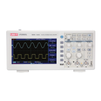
2.3 Control panel instructions
Keys on the control panel of the oscilloscope communication an
d control software (Fig 2
This indicated the current control status of the digital storage oscilloscope.
During “data transmission”, this status bar indicates the current control status of the oscilloscope. This
changes with the actual control status of the oscilloscope but you cannot control the current status of the
oscilloscope with this bar.
Coupling method (DC, AC, GND); Bandwidth suppression (On, Off); Filter type (low
stop); Digital filter (when the indicator light comes on the function is ON, when
the indicator light goes off the function is OFF); Reverse (when the indicator comes on the function is ON,
when the indicator light goes off the function is OFF); Prob
e (1X, 10X, 100X, 1000X).
Coupling method (DC, AC, GND); Bandwidth suppression (On, Off); Filter type (low
stop); Digital filter (when the indicator light comes on the function is ON, when
the indicator light goes of
f the function is OFF); Reverse (when the indicator light comes on the function is
ON, when the indicator light goes off the function is OFF); Probe (1X, 10X, 100X, 1000X).
Voltage range; Time base range
Equipment selection (USB, LAN, GPIB); ON/OFF (when the indicator light comes on
the function is ON, when the indicator light goes off the function is OFF); Data transmission (when the
indicator light comes on the function is ON, when the indicator light goes off the function is OFF);
Transmission interface (when the indicator light c
omes on the function is ON, when the indicator light goes
off the function is OFF).
 Loading...