UTD2000 Series User Manual
17
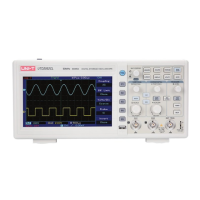
Figure 2-2 Simultaneous Display of Signal DC and AC Components
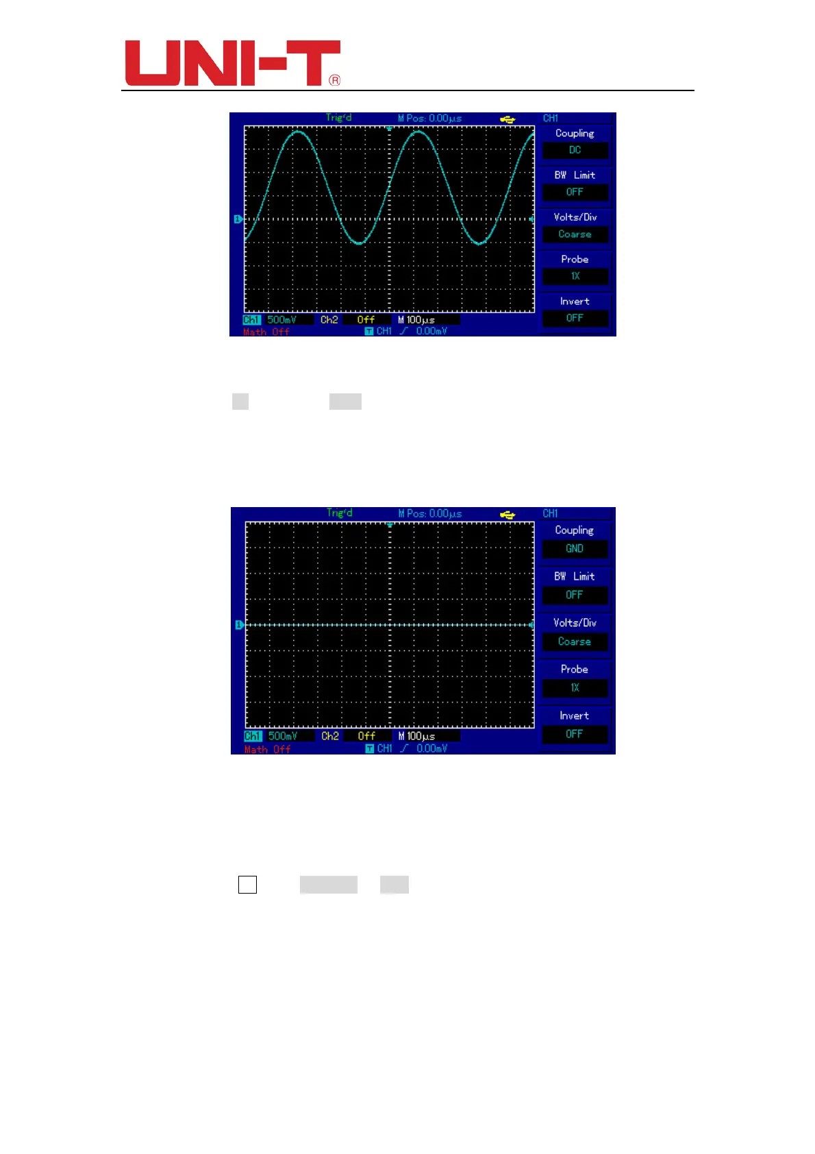
If you Press F1 to select as GND, to set CH1 to connect to the internal ground of the
instrument, both DC and AC components of the input signal are blocked. And, waveform
display is shown in figure below.
(Note: although no waveform is displayed on the screen in this mode, input signal is
still connected with channel circuit.)
Figure 2-3 Simultaneous Blocking of Signal DC and AC Components
2.2 Setting channel bandwidth Limited
You will be learning through the following example to change the bandwidth limited of
the input channel. Assuming that the input signal is a 40MHz sinusoidal signal connect to
CH1. If you press F2 to set BW Limit as OFF, there will be not any bandwidth limited to
CH1. And, you can see all the high-frequency component in measured signal as
waveform displayed is shown in the figure below.
 Loading...