UTD2000 Series User Manual
49
oscilloscope channel to 10X. Connect the CH1 to the circuit signal input terminal. Connect
CH2 to the output terminal.
Steps :
(1) To display CH1 and CH2 signals
① Press AUTO.
② Continue to adjust the horizontal and vertical range until you get the desired
waveform display.
③ Press F1 to select CH1. Adjust vertical position of the CH1 waveform by
turning the vertical position control knob.
④ Press F2 to select CH2. In the same way described above, adjust vertical
position of the CH2 waveform so that the waveforms of CH1 and CH2 do not overlap.
This will make observation easier.
2. Observing the delay caused by a sine wave signal passes through the circuit
and observing waveform changes.
① When measuring channel delay automatically:
Press MEASURE to display the automatic measurement menu.
Press F1 to enter the measurement type selection menu.
Press F4 to enter the time measurement parameters table.
Press F5 twice to go to page 3/3.
Press F2 to select delayed measurement.
Press F1, select CH1 and then press F2 to select moving to CH2, then press F5
to confirm.
You can see the delay value below “CH1-CH2 delay” in
the F1 zone now.
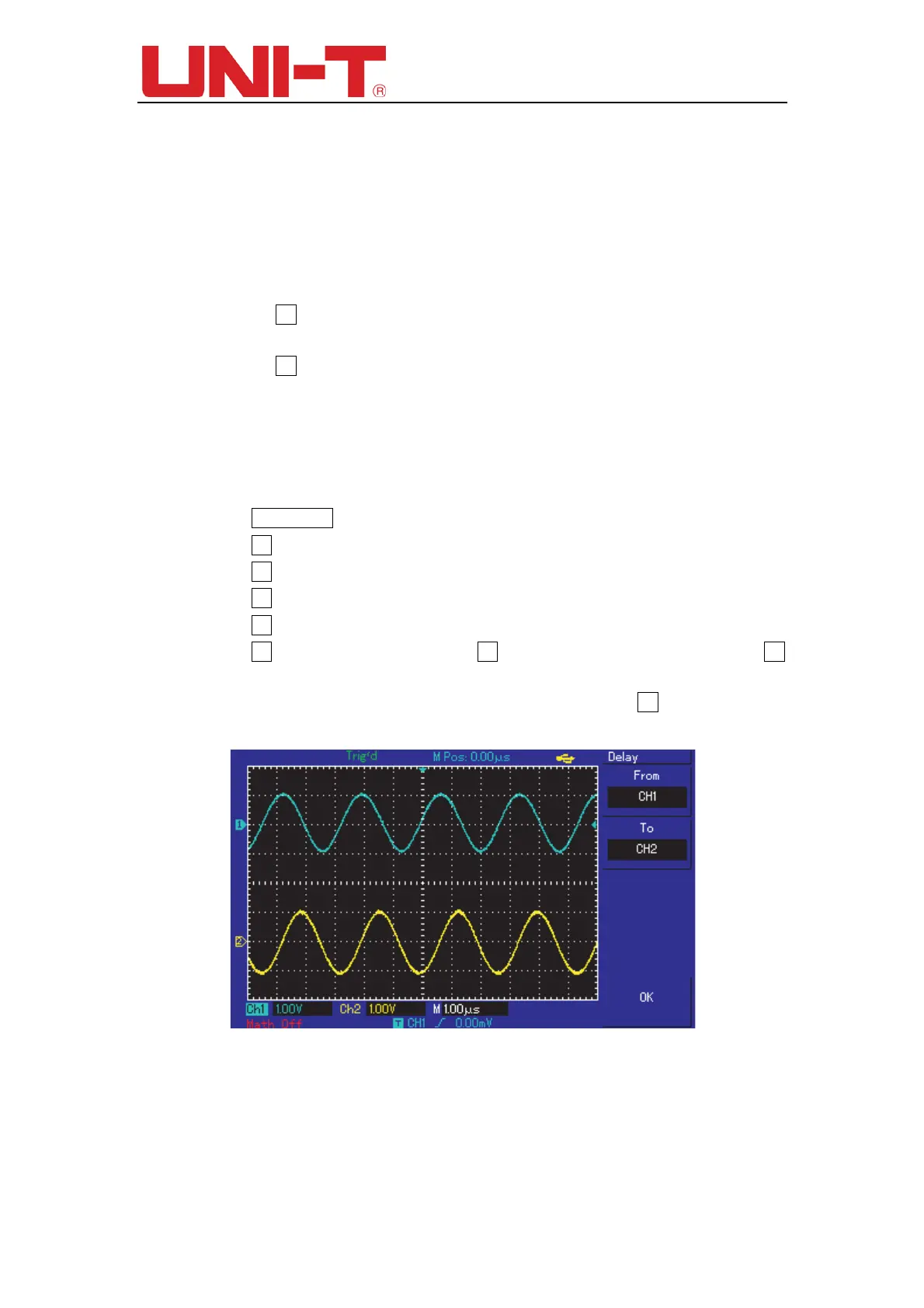
② Observe waveform changes (see the figure below).
Figure 12-2 Waveform delay
Example 3: Acquiring single signals
The advantage and special feature of your digital storage Oscilloscope
lie in its ability
to acquire non cyclical signals like pulse and glitch. To
acquire a single signal, you must
have transcendental knowledge of
that signal to set the trigger level and trigger edge. For
 Loading...