UTD2000 Series User Manual
27
DC Pass through DC and AC components of triggering signa
HF Reject high-frequency component of the triggering signal (over 80kHz signals)
LF Reject low-frequency component of the triggering signal (below 80kHz signals)
4.2 Pulse width trigger
For pulse width trigger, the trigger time shall be subject to pulse width of the triggering
signal. You can capture abnormal pulse by setting pulse width conditions.
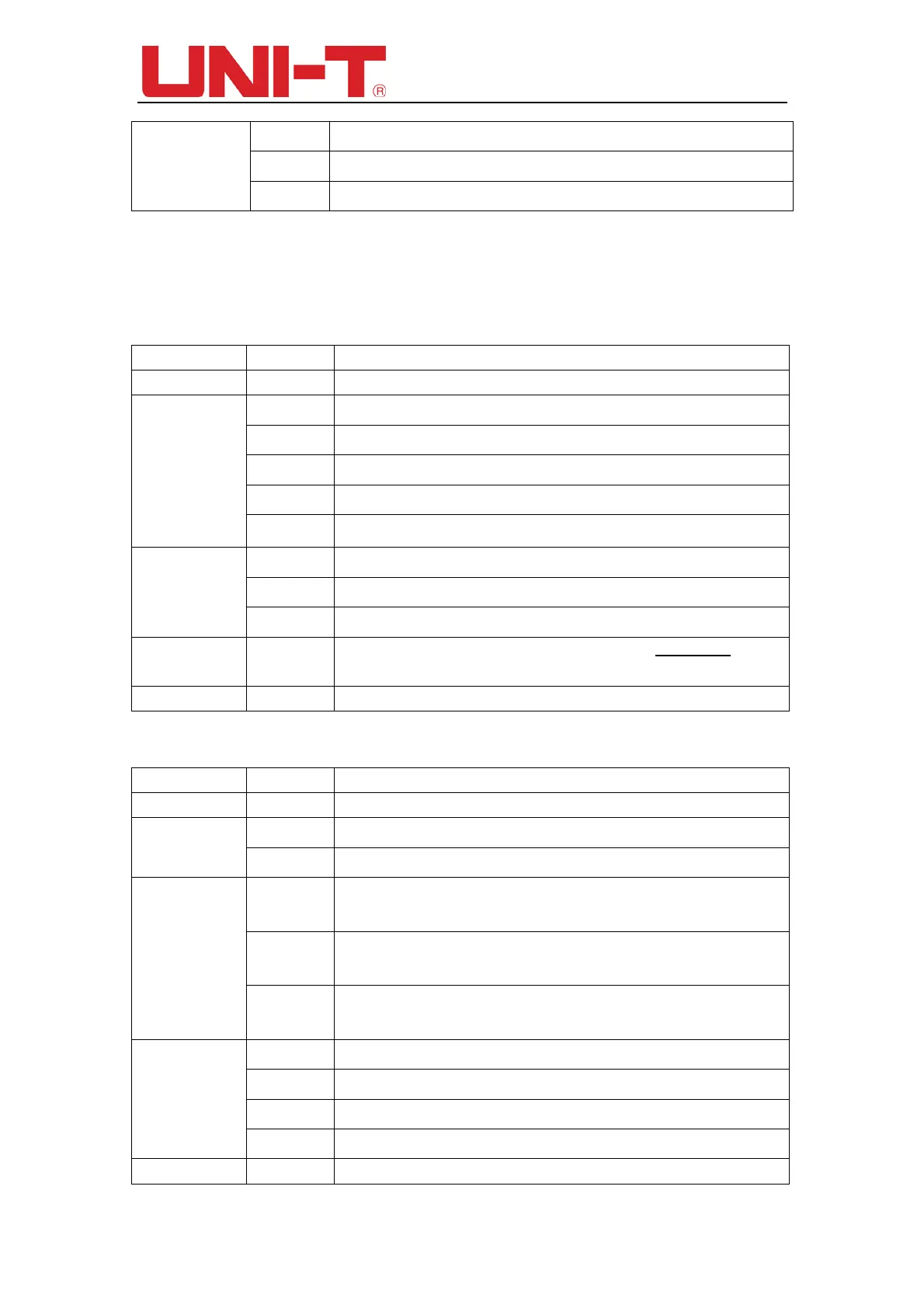
Table 4-2 Pulse width trigger menu (page 1)
Function Menu Setting Description
Type Pluse
Source
CH1 Set CH1 as the triggering signal source
CH2 Set CH2 as the triggering signal source
EXT Set external trigger input channel as the triggering signal source
AC Line Set AC power line as trigger source
Alter Set to Alternative trigger between CH1 and CH2 as signal source
Pulse width
conditions
> Trigger when pulse width is greater than Pulse Width setting values
< Trigger when pulse width is less than Pulse Width setting values
= Trigger when pulse width is equal than Pulse Width setting values
Pulse width
setting
Set the pulse width to between 20ns~10s by using the multi-purpose
knob on
the front panel。
Next 1/2 Go to next page
Table 4-3 Pulse width trigger menu (page 2)
Function Menu Setting Description
Type Pluse
Polarity
Positive Set the positive pulse width as trigger signal
Negative Set the negative pulse width as trigger signal
Mode
AUTO
Set to automatic trigger. The DSO will continuously perform data acquisition
without triggering signal.
Normal
Set to normal trigger. The DSO will only perform data acquisition when there is
triggering signal.
Single
Set to single trigger. The DSO will only perform 1 cycle of the data acquisition
when there is triggering signal.
Coupling
AC Block the DC component of triggering signal
DC Pass through DC and AC components of triggering signa
HF Reject high-frequency component of the triggering signal (over 80kHz signals)
LF Reject low-frequency component of the triggering signal (below 80kHz signals)
Previous 2/2 Go to previous page
 Loading...