UTD2000 Series User Manual
16
Chapter II Vertical System
Each channel for UTD2000 series DSO can be set independently through the vertical
system menu. After pressing CH1 or CH2 function key, the system shall display function
menu of CH1 or CH2 channel. See Table 2-1 below for description.
Table 2-1 Channel Menu
Function Menu Setting Description
Coupling
AC Block the DC component of input signal.
DC Pass through DC and AC components of input signal
GND Disconnect input signal
BW Limit
ON Limit bandwidth to 20MHz to reduce displayed noise.
OFF Turn off bandwidth limited
Volts/Div
Coarse Set vertical deflection factor by coarse adjustment based on 1-2-5 scale.
Fine
Rough adjustment setting range is further subdivided for fine adjustments to improve
vertical resolution.
Probe
1×
10×
100×
1000×
Please set the probe compensation system ratio to match the probe attenuation
coefficient of the probe to be used.
Invert
ON Activate reverse function of waveform. Waveform will be displayed reversely
OFF Waveform is displayed normally.
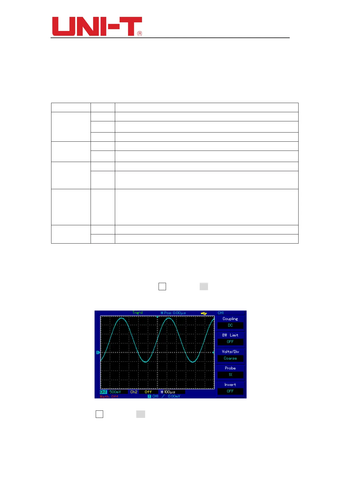
2.1 Setting coupling channel
You will be learning through the following example to change the coupling of the input
channel. If the measured signal connect to the CH1 channel is a sinusoidal signal
containing DC component. If your press F1 to select as AC coupling, to set the CH1 into
AC coupling mode. Then the DC component of the measured signal is blocked. Waveform
display is shown in figure below.
Figure 2-1 Blocked DC Component of Signal
If you press F1 to select as DC coupling, setting the CH1 to DC coupling mode. You
should be able to see both the DC and AC components of measured signals at CH1
channel as shown in figure below.
 Loading...