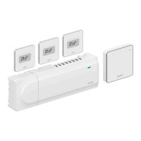
Quick Guide
Installation
1. Attach the full assembly, or parts of it, to the wall
either with a DIN rail or by using wall screws and
plugs.
2. Connect the actuators.
3. Connect a thermostat communication cable to
the controller, slave module, and/or the optional
star module. Note: Daisy chain bus topology is
recommended. See page 10, Communications
protocol for more information.
4. Connect a communication cable to the thermostat/
timer.
5. Check that all wiring is complete and correct:
• Actuators
• Heating/cooling switch
• Circulation pump
6. Ensure that the 230 V AC compartment of the
controller is closed and the fi xing screw is tightened.
7. Connect optional external sensor (compatible
thermostats only) and set the DIP switch (public
thermostat T-143 only).
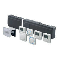
Function
Switch
Standard room thermostat
1234
ON DIP
Standard room thermostat together with a
fl oor temperature sensor
1234
ON DIP
Standard room thermostat, or system device,
together with an outdoor temperature sensor
1234
ON DIP
System device where the sensor input is used
for Comfort/ECO switch over function *
1234
ON DIP
Remote sensor
1234
ON DIP
* Closed = ECO
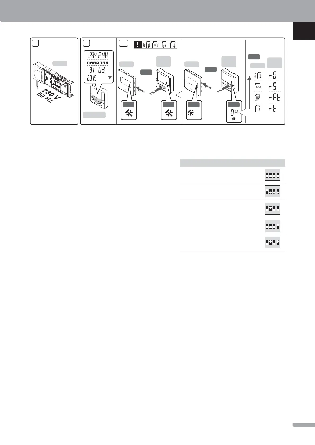
8. Connect the power cable to a 230 V AC wall socket,
or if required by local regulations, to a junction box.
9. Set time and date on thermostats or timer (digital
thermostat T-148 or timer only).
10. Select thermostat control mode (settings menu 04,
in digital thermostats only). Default: RT (standard
room thermostat).
Register thermostats, the timer and other system
devices, in that order (next page).
X-147
10
3 s
3 s
I-143/T-148
T-148
T-146
T-149
10.1
10.2
T-148
T-146
T-149
10.3
10.4
T-148
T-146
T-149
10.5
10.2 10.4
04
8 9
QUICK GUIDE
7
UPONOR SMATRIX BASE · QUICK GUIDE
UK
CZ
DE
DK
EE
ES
FI
FR
HR
HU
IT
LT
LV
NL
NO
PL
PT
RO
RU
SE
SI
SK
 Loading...