Connect circulation pump 2 to
controller (optional)
The controller can operate a second circulation pump,
which stops when there is no demand for heating or
cooling. See section 8.5 System parameter settings for
more information.
NOTE!
See the documentation from the circulation
pump supplier as well as relevant Uponor
wiring diagrams before connecting the pump.
NOTE!
The second circulation pump can be
controlled by an optional extra wireless
thermostat (Move PLUS only).
NOTE!
When connecting a second circulation
pump, the terminal block connectors will be
unavailable for a chiller.
Warning!
There is 230 V (5 A) power in the controller to
supply circulation pump 2 when the controller
is connected to the mains.
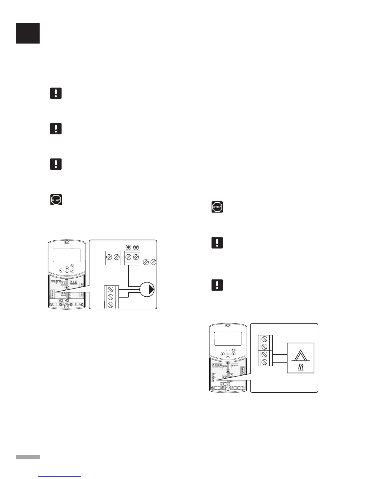
The illustration below shows the circulation pump
connected to the controller.
N
L
1. Ensure that the power is disconnected from both
the controller and the circulation pump.
2. Connect the L, N, and Earth wires from the
circulation pump to the corresponding labelled
terminal block connections at position P2/COLD in
the controller.
3. Secure the wires with a cable clamp in the
controller.
Connect heating system or boiler
to controller (optional)
The controller includes a boiler relay. It can be used to
send a signal to either fire the heat source or to power
open a 2-port motorised zone valve, positioned on the
supply to the underfloor heating manifold. If the relay
is used to open a zone valve then, the volt free auxiliary
contacts on the zone valve should be used to fire the
heat source.
Alternatively, the boiler relay can be used to send
a demand signal to an electrically operated water
temperature controller. The additional contacts on the
water temperature controller should then be used to fire
the heat source.
• The controller uses a dry contact sensing input on
the terminal block to control a heating system or
boiler.
• The output uses 230 V (5 A) as a signal to produce
heating. The signal from the controller is triggered
by a thermostat or an external source connected to
inputs In1 or In2 in the controller.
Warning!
There is 230 V (5 A) power in the controller
to manage the heating system or boiler, when
the controller is connected to the mains.
NOTE!
See the documentation from the heating
system or boiler supplier as well as relevant
Uponor wiring diagrams before connecting
the heating system or boiler.
NOTE!
This connection requires a dry contact
sensing input in the boiler.
The illustration below shows the connection of a
heating system or boiler to the controller.
1. Ensure that the power is disconnected from both
the controller and the heating system.
2. Connect the boiler to the connection labelled HEAT
in the controller.
UK
CZ
DE
DK
EE
ES
FI
FR
HR
HU
IT
LT
LV
NL
NO
PL
PT
RO
RU
SE
SK
22
UPONOR SMATRIX MOVE/MOVE PLUS · INSTALLATION AND OPERATION MANUAL