INSTALLATION - STEP 6
ELECTRICAL CONNECTIONS
TO THE CONTROL
IMPORTANT: Test to be certain
no voltage is present in any wires.
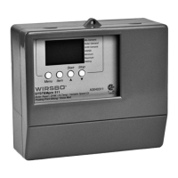
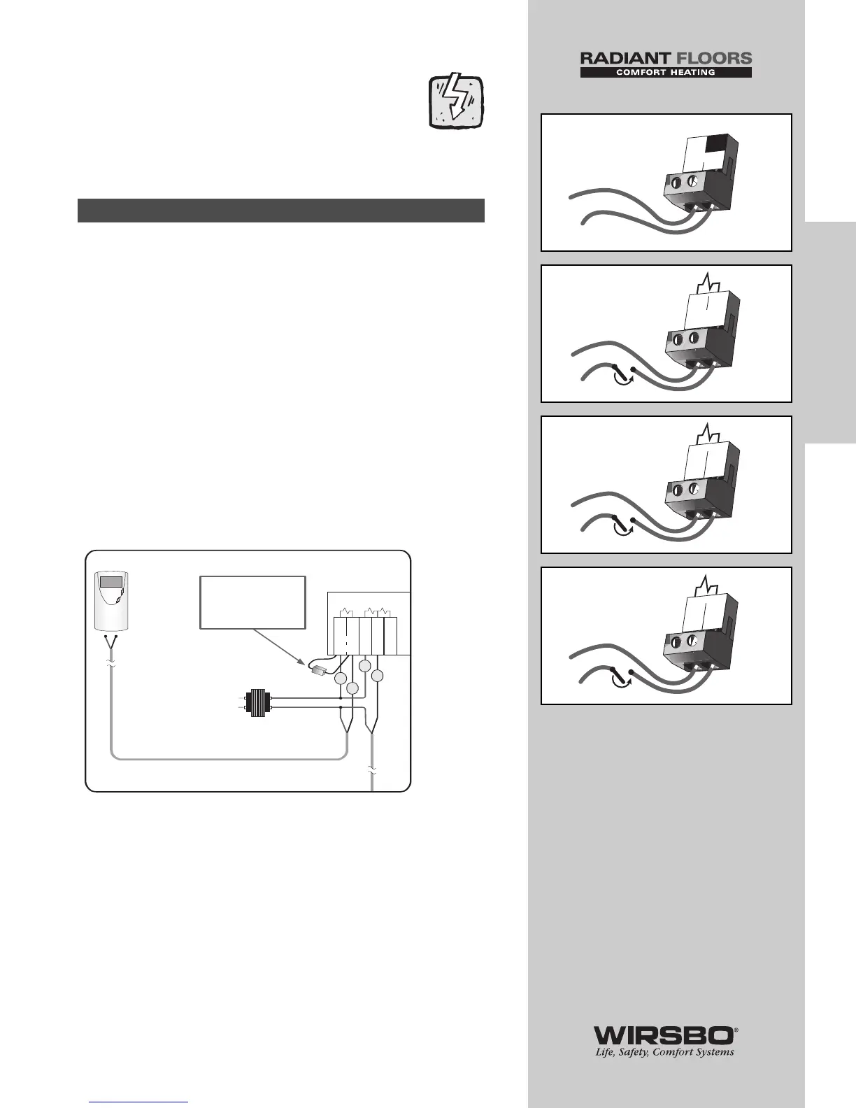
120 VAC Power (See fig. a)
• Provides power to microprocessor and control display as well
as power to Boil P3 terminal (8) from Power L terminal (7)
• Connect 120 VAC power supply to Power L and Power N
terminals (6 and 7)
Demand Connections
Demand to the control is generated from a thermostat zone
control module or external relay. This connection must have
24 VAC supplied to the demand terminals
Mixing Demand (See fig. b)
• Apply a voltage between 24 VAC and 240 VAC across Mixing
Demand terminals (1 and 2)
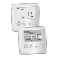
Mixing Demand with Wirsbo Thermostat
NOTE: When connecting a Wirsbo Thermostat WT1
or WT2 directly to the Mix Demand Terminals 1 and 2,
a 0.5 watt 1000 ohm resistor needs to be installed
parallel as shown. A packet with the resistor and
schematic is included in the box.
Boiler Demand (See fig. c)
• Apply a voltage between 24 VAC and 240 VAC across
Boil Dem and Com Dem terminals (3 and 4)
DHW Demand (See fig. d)
• Apply a voltage between 24 VAC and 240 VAC across DHW
and the Com Dem terminals (4 and 5)
Powered Input Connections
23
INSTALLATION
INSTALLATION - Step 6 - Electrical Connections to the Control