Test the Power Supply
1) Make sure exposed wires and bare terminals are not in
contact with other wires or grounded surfaces
2) Turn on the power and measure the voltage between the
Power L and Power N terminals (6 and 7) using an AC
voltmeter, the reading should be between 108 and 132 VAC
Test the Powered Demand Inputs
Voltage Readings for ALL Demand Devices
(described below)
1) When any of the demand devices described above calls for
heat, you should measure between 20 and 260 VAC at the
terminals
2) When these demand devices are off, you should measure
less than 5 VAC
Mixing Demand (if used)
• Measure voltage between Mix Demand terminals (1 and 2)
Boiler Demand (if used)
• Measure voltage between Boil Dem and Com Dem terminals
(3 and 4)
DHW Demand (if used)
• Measure voltage between DHW Dem and Com Dem
terminals (4 and 5)
Test the Outputs
IMPORTANT NOTE FOR ALL OUTPUT DEVICES:
Once you have verified a device operates properly,
shut off the power to the device and remove the
jumper installed during the testing procedure below.
If any device fails to start, see troubleshooting
information on page 32.
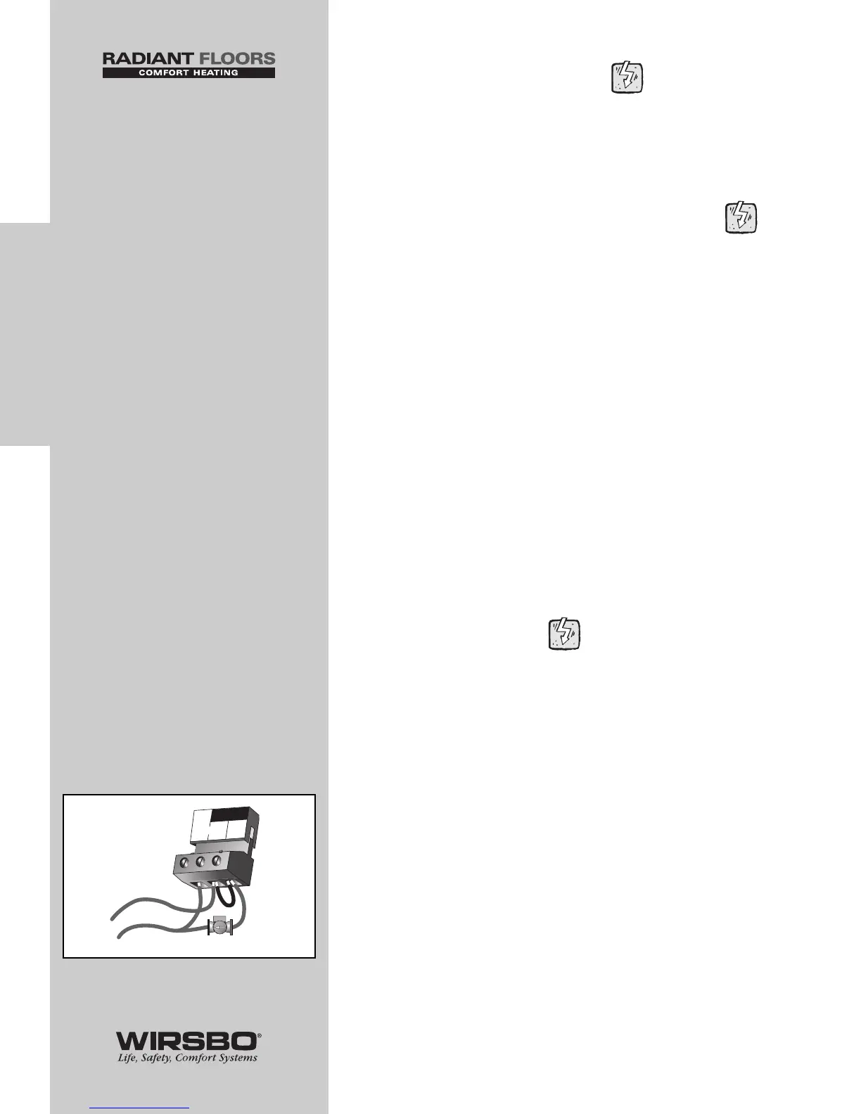
Primary Pump (Boil P3) — connected to
terminal (8) (See fig. a)
1) Make sure that power to terminal block is off
2) Install a jumper between Power L and Boil P3 terminals
(7 and 8)
3) When power is applied to the Power L and Power N terminals
(7 and 6) the primary pump should start
30
INSTALLATION
INSTALLATION - Step 7 - Testing the Wiring