WARNING: Do not apply power to these
terminals as this will damage the control.
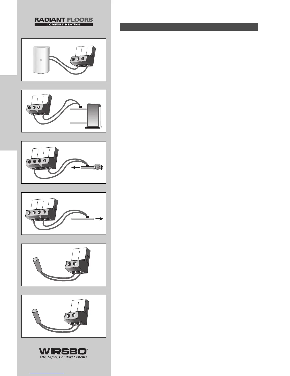
Connect the two wires from sensors to terminals described
below:
8) Outdoor Sensor S4 wires to Com
and Out terminals (27 and 29) (See fig. l)
• Measures outdoor air temperature
9) Boiler Sensor S3 wires to Com
and Boil S3 terminals (24 and 26) (See fig. m)
• Measures supply water temp from boiler
10) Mixing Supply Sensor S1 wires to Com
and Mix S1 terminals (20 and 23) (See fig. n)
• Measures the supply temperature after the mixing device
NOTE: Sensor is normally attached downstream
of mixing system pump (P1).
11) Mixing Return Sensor S5 wire to Com
and Ret S5 terminals (20 and 22) (See fig. o)
• Measures fluid return temperature from snow melting slab
NOTE: This sensor is only used when the
Snow Melting/Mixing Reset DIP switch is
set to the Snow Melting position
12) Mix 10K Sensor to Com and Mix 10K
terminals (20 and 21) (See fig. p)
• Works with indoor sensor, slab sensor, or zone control
sensor
13) DHW Sensor S6 to Com and DHW S6
terminals (27 and 28) (See fig. q)
• Measures temperature in DHW (Domestic Hot Water) tank
Sensor Connections (8-13)
26
INSTALLATION
INSTALLATION - Step 6 - Electrical Connections to the Control