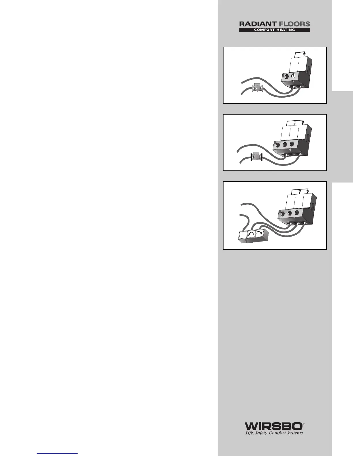
5) Mixing System Pump (Mixing Pmp P1)
(See fig. i)
Mixing Pmp P1 terminals (11 and 12) are isolated outputs.
No power is available on these terminals from the control.
• Use terminals as a switch to either make or break power
to mixing system pump
• As an isolated contact, it may switch a voltage between
24 VAC and 240 VAC
6) Variable Speed Injection Pump (Cls/P4)
(See fig. j)
The SYSTEMpro 311 can vary the speed of a pump motor with
locked rotor current of less than 2.4 A (most small wet rotor
circulators may be used as described in APPENDIX I - page 85).
• If using a variable speed injection pump, connect one of
the wires from variable speed injection pump to Cls/P4
terminal (19)
• Connect other wire on variable speed injection pump to live
(L) side of 120 VAC power supply
• Connect Pwr Mix terminal (17) to neutral (N) side of 120 VAC
power source
7) Mixing Valve Actuator (See fig. k)
If a mixing valve is used:
• Connect one side of 24 VAC power to Pwr Mix terminal (17)
on control
• Connect output relay Opn (18) to the "open" terminal of
actuating motor
• Connect output relay Cls/P4 (19) to the "close" terminal of
actuating motor
• Connect second side of 24 VAC circuit to common terminal
of actuating motor
NOTE: The SYSTEMpro 311 has an internal
overload fuse rated at 2.5 A 250 VAC — contact
your Wirsbo sales representative for repair
information if fuse is blown.
25
INSTALLATION
INSTALLATION - Step 6 - Electrical Connections to the Control