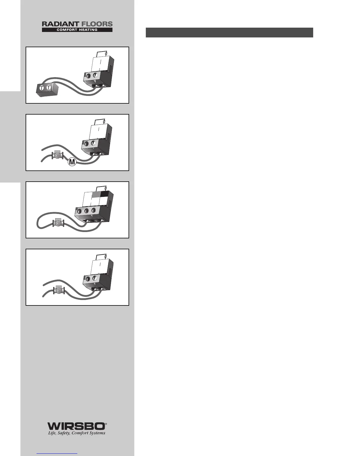
1) Boiler Contact (See fig. e)
Boiler terminals (15 and 16) are an isolated output. No power
is available on these terminals from the control.
• Use terminals as switch to make or break the boiler circuit
• When the SYSTEMpro 311 requires the boiler to fire, contact
closes between terminals 15 and 16
2) DHW Pump/Valve Contact (See fig. f)
DHW P6/Vlv terminals (13 and 14) are an isolated
output. No power is available on these terminals from the
control.
• Use terminals as switch to either make or break power to
DHW pump or valve
• As an isolated contact it may switch a voltage between 24
VAC and 240 VAC
3) Primary Pump Contact (Boil P3) (See fig. g)
Boil P3 output terminal (8) is a powered output. When relay in
the SystemPro 311 closes, 120 VAC is provided to Boil P3
terminal (8) from Power L terminal (7).
• To operate primary pump, connect one side of primary pump
circuit to terminal (8) and second side of pump circuit to
neutral N terminal (6) side of 120 VAC power supply
4) Boiler Demand Pump (Boil Dem Pmp P7)
(See fig. h)
Boil Dem Pmp P7 terminals (9 and 10) are an isolated output.
No power is available on these terminals from the control.
• Use terminals as a switch to make or break power to the
boiler system pump
• As an isolated contact, it may switch a voltage between
24 VAC and 240 VAC
Output Connections (1-7)
24
INSTALLATION
INSTALLATION - Step 6 - Electrical Connections to the Control