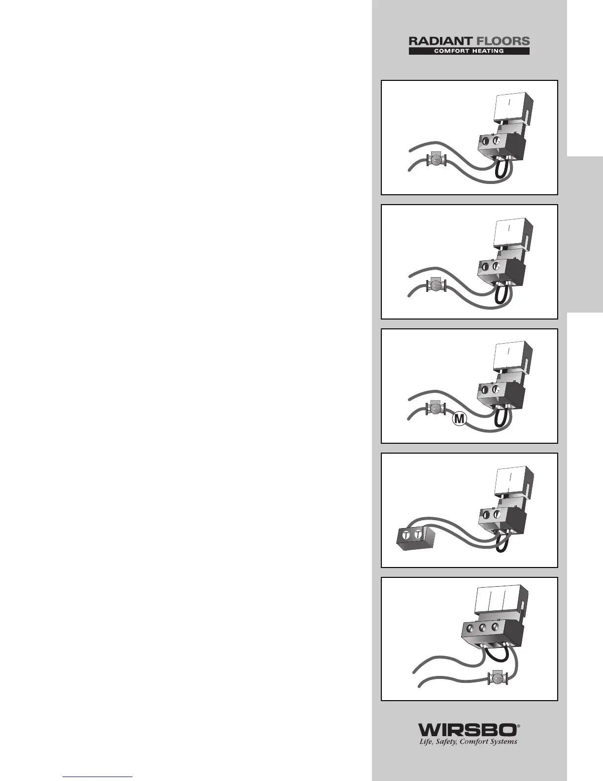
Boiler Demand Pump (Boil Dem Pmp P7) —
terminals (9 and 10) (See fig. b)
1) Make sure power to the pump circuit is off
2) Install a jumper between terminals (9 and 10)
3) When pump circuit is powered up, boiler demand pump
should start
Mixing System Pump (Mixing Pmp P1) —
terminals (11 and 12) (See fig. c)
1) Make sure power to the pump circuit is off
2) Install a jumper between terminals (11 and 12)
3) When the pump circuit is powered up, mixing system pump
should start
DHW Pump or Valve (DHW P6 / Vlv) —
(13 and 14) (See fig. d)
• Make sure power to the pump or valve circuit is off
• Install a jumper between terminals (13 and 14)
• When the DHW circuit is powered up, the DHW pump should
turn on or the DHW valve should open completely
Boiler — connected to the Boiler terminals
(15 and 16) (See fig. e)
• Make sure power to the boiler circuit is off
• Install a jumper between the terminals (15 and 16)
• When the boiler circuit is powered up, the boiler should fire
NOTE: Boiler may have a flow switch that prevents
firing until the primary pump (P3) is running.
Variable Speed Injection Pump (VSP P4) —
(17 and 19) (See fig. f)
• Make sure power to terminal block is off
• Install a jumper between the Pwr Mix and Cls/P4 terminals
(17 and 19)
• When the variable speed pump circuit is powered up, the
variable speed pump should operate at full speed
31
INSTALLATION
INSTALLATION - Step 7 - Testing the Wiring